8
©
2002
Directed Electronics, Inc.
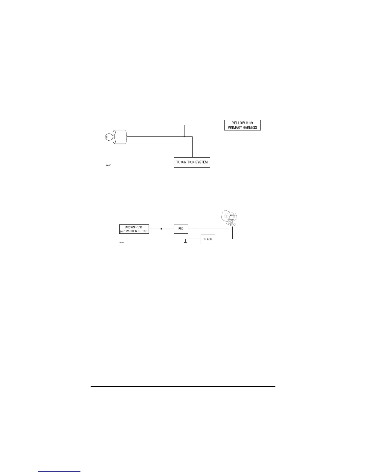
H1/9 YELLOW (+) ignition input
Connect this wire to the (+) 12 volts ignition wire. This wire is pre-wired to the starter kill relay and
must show (+) 12 volts with the key in RUN position and during cranking. Take great care that this
wire cannot be shorted to the chassis at any point.
\\\\\\\
H1/10 BROWN (+) siren output
Connect this to the RED wire of the Revenger® siren. Connect the BLACK wire of the siren to (-)
chassis ground, preferably at the same point you connect the control module’s BLACK ground wire.
H1/11 RED (+)12V constant power input
Before connecting this wire, remove the supplied fuse. Connect to the battery positive terminal or
the constant 12V supply to the ignition switch.
NOTE: Always use a fuse within 12 inches of the point you obtain (+)12V. Do not use the 15 fuse
in the harness for this purpose. This fuse protects the module itself.
H1/12 RED/WHITE high current output from on-board channel 2 (trunk release) relay
Whenever the button(s) controlling channel two is pressed for 1.5 seconds, the on-board relay is
activated and will stay activated as long as the transmission continues. This relay is often used for
trunk release. The relay can drive circuits up to 20 amperes. The polarity of this output is deter-
mined by the connection of the input wire H2/A in the Relay Harness.
NOTE: If the input wire H2/A is not connected, there will be no output from the relay when it is
activated.