© 2009 Directed Electronics. All rights reserved.
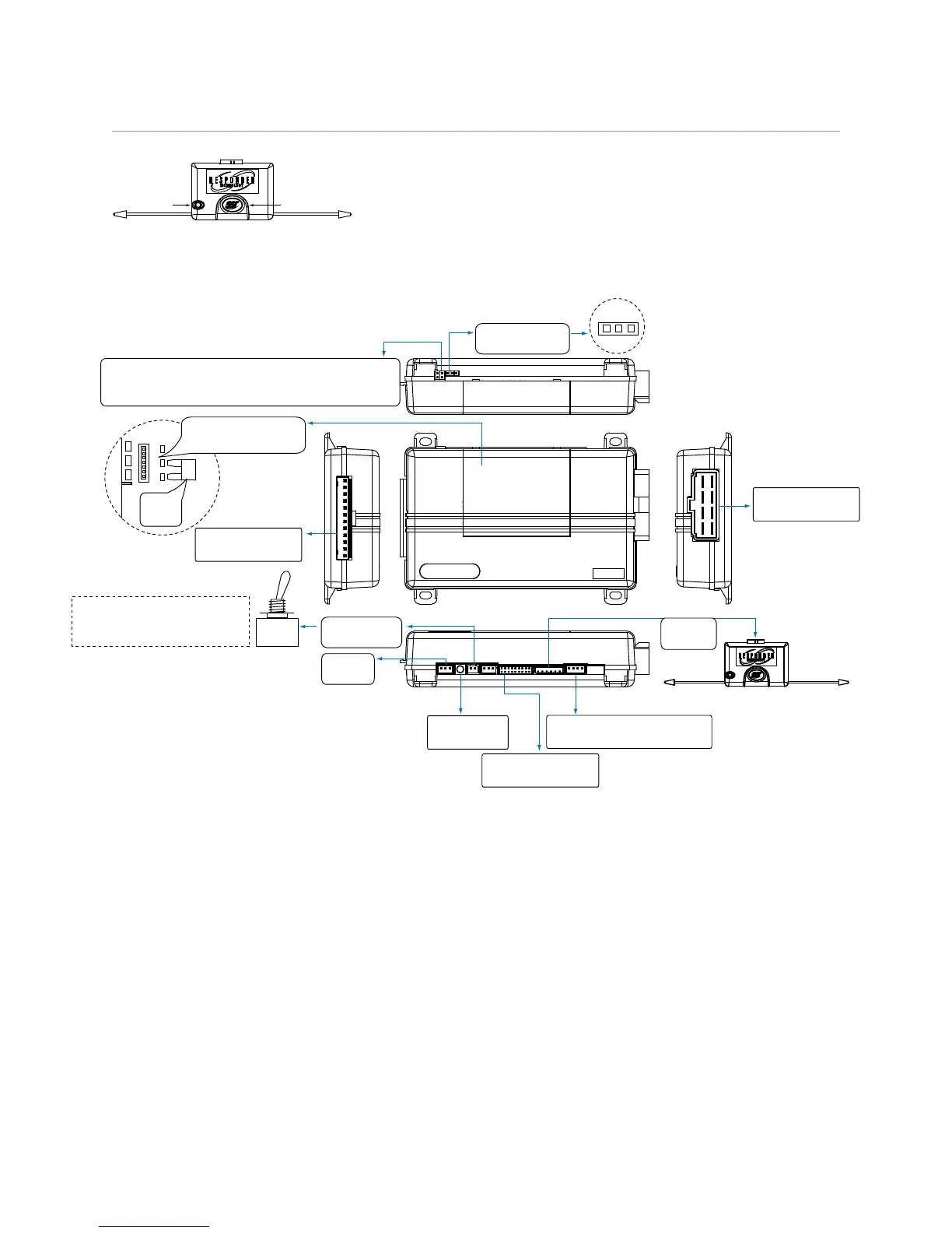
CPU1
10A FUSE
MINI ATM
RPN: 8540
LIGHT FLASH POLARITY
(10A (MAXIMUM) FUSE JUMPER)
+ -
58 7 6
1234
Bitwriter
Port
Neutral Safety
Switch
Horn Input
Polarity Jumper
1
10 9 8 7 6
12345
1
1 8
51
1 3
10
12
18
10
9
1
1 12
D2D Port (for external
Xpresskit interface module)
10A FUSE
MINI ATM
RPN: 8540
LIGHT FLASH POLARITY
(10A (MAXIMUM) FUSE JUMPER)
+ -
ON
IMPORTANT! Neutral Safety
switch must be plugged in
and in the ON position
D2D jumpers; Factory setting is horizontal position.
Most Xpresskit modules use this setting, check the
Xpresskit installation guide for the specific setting.
RF Port
for IVU
Control Center
Temperature
Sensor
+ -
Main Harness (H1)
(see wiring tables)
H2 Harness
(see wiring tables)
Remote Start (H3)
(see wiring tables)