Replacing the base assembly
New Replacement Units
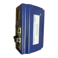
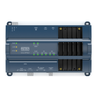
EC-BOS-6
AX
Mounting and Wiring Instructions
Part Number: 05DI-HIBS6AX-10 Revised: February 2008
23
Step 4
Unplug all Ethernet, serial, LON, and modem connectors from the EC-BOS-6
AX
, and unplug its earth
ground wire.
Step 5
If I/O accessory modules are installed:
–
If DIN rail mounting with DIN end-clips was used, you may be able to remove the DIN rail end clip
that secures the EC-BOS-6
AX
end of the assembly and then slide the EC-BOS-6
AX
away from the rest
of the assembly. Then you can remove the EC-BOS-6
AX
from the DIN rail (see Figure 1 on page 6),
leaving the mounting and wiring of I/O modules untouched. In this case, after removing the
EC-BOS-6
AX
from the DIN rail, skip ahead to Step 6.
–
If tab (screw) mounting was used instead of DIN rail mounting, or if a combination of DIN rail
mounting and tab screws (into the EC-BOS-6
AX
’s “accessory side” tab holes, see last page), you will
need to remove the accessory modules first, before removing the EC-BOS-6
AX
. In this case:
a. Making a careful note of all wiring terminations, unplug the I/O connector plugs and earth ground
wires from the installed I/O modules.
b. Remove the installed accessory modules, starting with the end module. Modules may be secured
by screws in mounting tabs or clipped to a DIN rail, or fastened by some sombinations. See
Figure 1 on page 6 for details on removal from (and mounting onto) the DIN rail.
c. Remove any screws fastening the EC-BOS-6
AX
and remove it (see Figure 1 on page 6).
Step 6
Remove the cover from the old EC-BOS-6
AX
(see “Removing and Replacing the Cover,” page 7).
Note the position of installed option boards, if any. You must transfer them to the replacement
EC-BOS-6
AX
.
Step 7
Remove the option boards from the old EC-BOS-6
AX
and install them into the replacement
EC-BOS-6
AX
, if applicable. See “Mounting Option Cards,” page 8, for more details.
Step 8
Mount the replacement EC-BOS-6
AX
as it was previously, using the same DIN rail location and/or
screws.
Step 9
Reconnect/remount any removed accessory modules, being careful to replace in the same order, using
the same DIN rail location and/or screws. Secure all accessory modules as done previously.
Step 10
Reconnect the earth ground wires to the EC-BOS-6
AX
grounding lug and any installed accessory
modules.
Step 11
Reconnect any Ethernet, serial, and modem connectors to the EC-BOS-6
AX
and any installed
accessory modules.
Step 12
If using I/O modules, and any of your I/O points have voltage, turn the devices back on or reconnect
power to them.
Step 13
Restore power to the EC-BOS-6
AX
. It should boot up as a new unit (see “Check the Status LEDs,”
page 17).
Step 14
Using the Niagara
AX
platform tools, re-commission the EC-BOS-6
AX
, and install the saved station
database. For more details, see the EC-BOS
AX
Install and Startup Guide.