3
EN
NOTE: A maximum of four (4) total option modules are supported.
Separate limits may exist in the controller’s license, which can further
limit options.
Description
EC-BOS-9
DIN-mount, 24Vac/dc (50/60Hz) powered, area controller. See the
product data sheet for complete specications. See the EC-BOS-9
Mounting and Wiring Guide for complete hardware installation details.
Included in this Package
is package includes the following items:
• EC-BOS-9
• MicroSD card in plastic case. See “Preparation”.
• Two 3-position RS485 connector plugs, one 2-position power
connector, and a grounding wire.
Material & Tools Required
• One of the following:
– UL listed, Class 2, 24Vac transformer, rated at minimum of 24Va.
A dedicated transformer is required (cannot power additional
equipment), or
– User supplied UL Listed Class 2 or LPS AC power adapter: 24Vdc,
capable of supplying at least 1A (24W). Optional barrel connector
plug (9.5mm L x 5.5mm OD x 2.1mm ID) or
– Wall-mount AC power adapter with barrel connector plug.
• DIN rail, type NS35/7.5 (35mm x 7.5mm) and DIN rail end-clips
(stop clips), recommended for any installation that includes option
modules. You may also mount the Controller on a panel.
• Suitable tools and fasteners for mounting the unit and any
accessories.
Preparation
If using a microSD card, insert the card before mounting a new
controller.
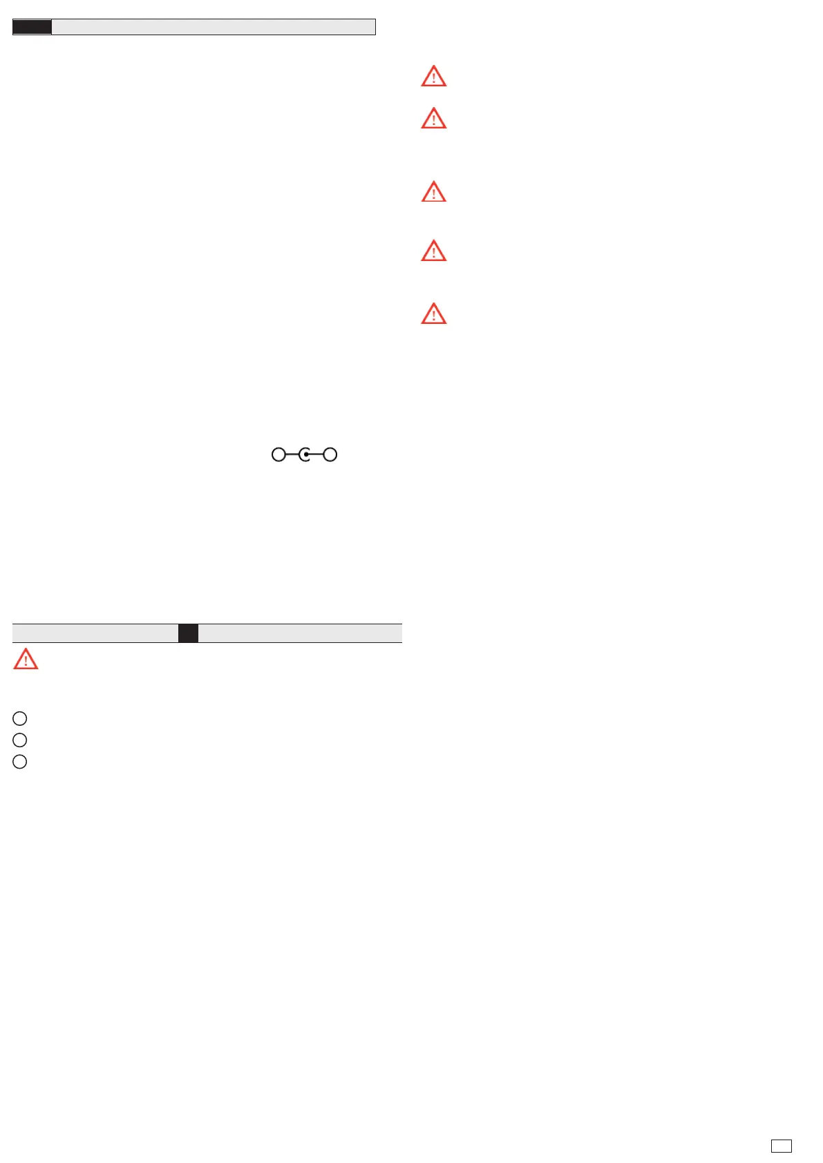
Install MicroSD Card, see image
1
Disconnect all power to the controller before removing or
inserting the microSD card. Otherwise, equipment damage is likely to
occur.
1
Access shutter for microSD card (slide to open or close.)
2
Card carrier inside controller.
3
MicroSD card to insert or remove from card carrier. Insert card
label-side up, until spring catch latches. If properly inserted, the card
is behind the shutter track. To remove card, push and release card.
NOTE: e microSD card is used to store backups. Backups, once
generated, are encrypted with a system passphrase that is stored in the
controller. You must re-enter this same passphrase to restore a backup
from the microSD card, using a serial connection to the unit’s Debug
port.
Warnings:
Disconnect power before installation or servicing to prevent
electrical shock or equipment damage.
To reduce the risk of re or electrical shock, install in a controlled
environment relatively free of contaminants.
Cautions:
Remove all power to controller before attaching (plug in) or
detaching (unplug) any option module, to prevent possible equipment
damage.
Removal of the controller’s cover is not required. No congurable
or user-serviceable items (such as jumpers or a battery) require cover
removal.
Protect against unauthorized access to your network systems by
restricting physical access to this controller.
Mounting
Mount the controller in a UL approved NEMA Type 1 enclosure. Make
sure to provide adequate clearance for wiring, servicing, and module
removal.
Environmental Requirements
NOTE: is product is for indoor use only, altitude to 2,000m (6,562
.).
Ambient conditions must be within the range of:
• Operating Temperature: -20°C to 60°C (-4°F to 140°F).
• Storage Temperature: -40°C to 85°C (-40°F to 185°F).
• Relative humidity: 5% to 95% non- condensing.
• Pollution Degree 2
• Supply (mains) voltage requirements are:
– Allowable voltage uctuation to +/-10%.
NOTE: Horizontal mounting is required to achieve maximum heat
dissipation and meet the operating temperature upper limit. Any other
mounting orientation reduces this upper limit.
 Loading...


