10 / 20
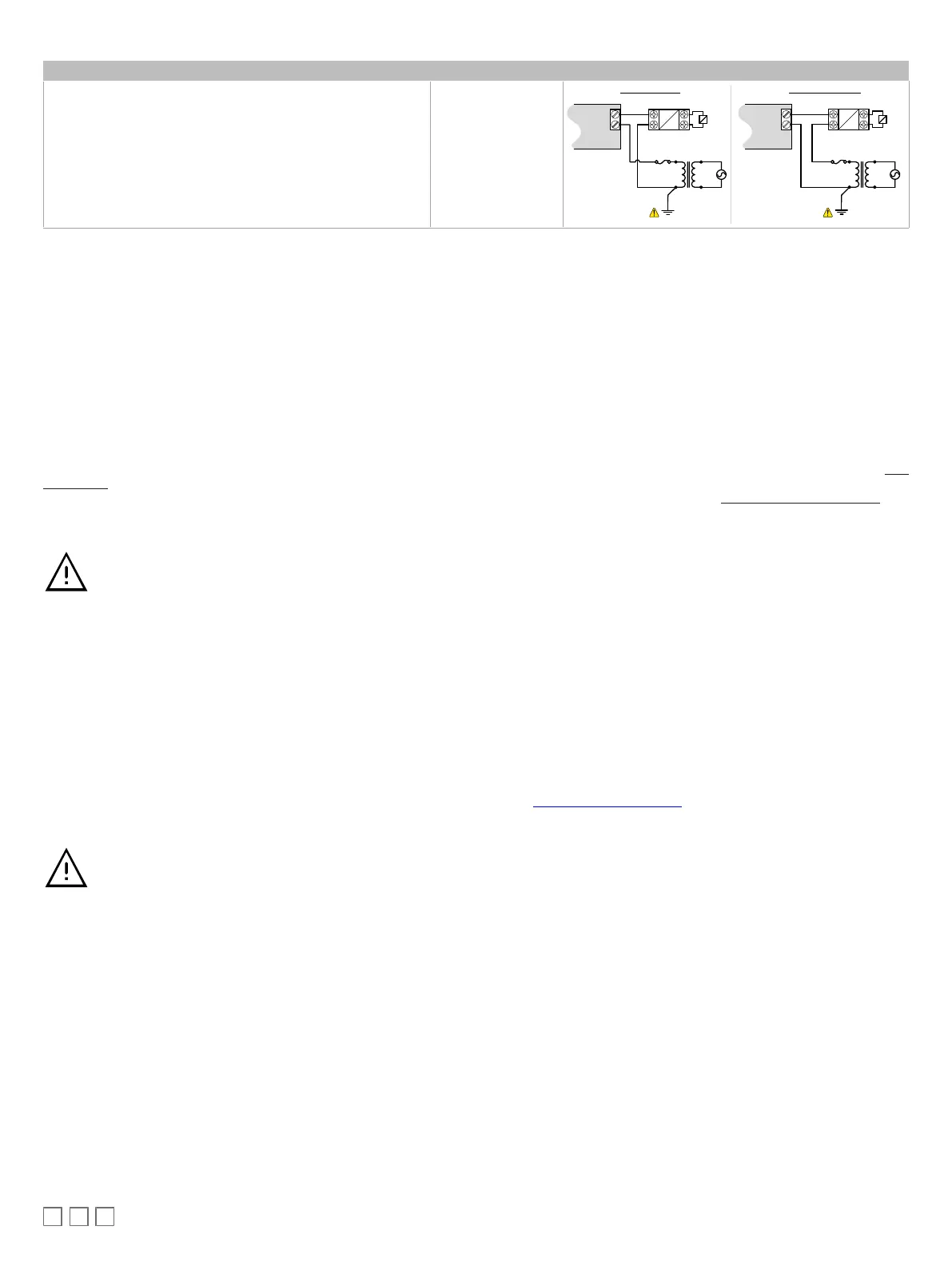
Control Output Type Output Designation Output Connection Diagram
£ 24VAC
externally
-powered triac output controlling a relay
1
with
line and neutral switching.
£ Ensure that the transformer’s secondary winding is grounded
as shown.
DOx
DOx
Cx
24VAC Relay
A2
A1
Transformer
AC
Electrical
System Ground
Fuse: 4A Max.
Fast Acting
24VAC
Load
DOx
Cx
24VAC Relay
A2
A1
Transformer
AC
Electrical System
Ground
Fuse: 4A Max.
Fast Acting
24VAC
Load
Line Switching Neutral Switching
Table4: Output Wiring
1. Maximum output current for all digital triac outputs is 0.5A continuous or 1A @ 15% duty cycle for a 10-minute period.
Subnet-Wiring
The subnet is used to connect a range of Allure Series Communicating Sensors:
£ The Allure EC-Smart-Vue Series sensor is a communicating room temperature sensor with backlit display graphical menus and VAV balancing ca-
pabilities.
£ The Allure EC-Smart-Comfort and Allure EC-Smart-Air Communicating Sensors are a range of communicating room temperature sensors.
Connect the Allure Series to the controller’s
Subnet Port
with a standard Category 5e Ethernet patch cable fitted with RJ-45 connectors. Refer to the Net-
work Guide for extensive information and requirements for the connection of the Allure Series. It contains information about network topology and length,
cable type, setting the Subnet ID, etc. It can be downloaded from the
www.distech-controls.com
website. See also the Hardware Installation Guide sup-
plied with the Allure Series.
If you make your own patch cable, see the Allure Series Hardware Installation Guide.
Protect the controller’s connector from being pulled on when a cable to the Allure Series is connected. Create a
strain-relief by looping the cable and attaching it to a solid object with a nylon tie so that a tug on the cable will not
pull out the connector on the controller.
Subnet Wiring with the ECB‑600 Series Controller
ECx-400 series IO Extension Modules are connected to the
SUBNET
– and
SUBNET+
terminals of the ECB‑600 series controller. The Network Guide
provides extensive information and requirements to implement the subnetwork for the ECx-400 series IO Extension Modules. It contains information
about network length, cable type, controller addressing, etc. It can be downloaded from our website. See also the Hardware Installation Guide supplied
with the ECx-400 series IO Extension Module.
Communications Wiring
The Network Guide provides extensive information and requirements to implement a BACnet MS/TP network. It contains information about network and
sub network length, cable type, device addressing, etc. It can be downloaded at the
www.distech-controls.com
website. For optimal performance, use
Distech Controls 24AWG (0.65 mm) stranded, twisted pair shielded cable or refer to the Network Guide for cable specification. The BACnet MS/TP com-
munication wire is polarity sensitive and the only acceptable topology is to daisy-chain the cable from one controller to the next.
As shown in BACnet MS/TP Communications Wiring:
£ The first and last daisy-chained BACnet MS/TP device must have its EOL resistors enabled / installed. All other
devices must have their EOL resistor disabled (default factory setting).
£ When the BACnet MS/TP data bus is connected to a following device, twist data bus shields together.
£ Isolate all shields with electrical tape so there is no exposed metal that can touch ground or other conductors.
£ The shield of the data bus must be connected to the electrical system ground at only one point – usually at one
end of the bus as shown below.
£ Connect no more than 50 devices to a BACnet MS/TP data bus.