11 / 20
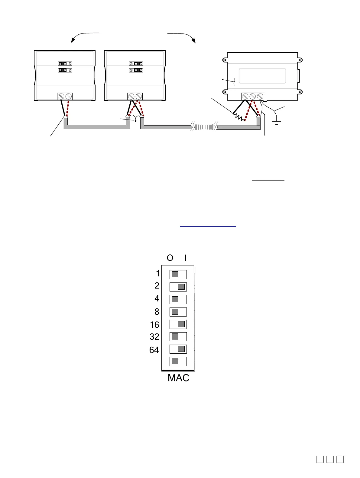
Data Bus Shield: Connect
to the ‘S’ terminal
Typical BACnet Device
First and last daisy-chained device:
-
- EOL Jumpers are ON
All other Devices::
- EOL Jumpers are OFF
EOL ON: For the EC-BOS
AX
as the first or last daisy
chained device:
- OPTIONALLY set the EOL
jumper internally
- AND add a 120 Ohm EOL
resistor as shown here
NET+
NET-
Typical BACnet Device
NET+
NET-
Typical EC-BOS
AX
Device
EOL ON EOL OFF
+-
S
Data Bus: Shielded Twisted Pair Cable
Data Bus Shield:: Isolate with
electrical tape
Data Bus Shields: Twist
together and isolate
with electrical tape
Up to 50 Devices Total
1
2
0
Ω
The shield of the
data bus must be
connected to the
electrical system
ground at only one
point – usually at
one end of the bus
as shown.
Figure11: BACnet MS/TP Communications Wiring
If inserting multiple wires in the terminals, ensure to properly twist wires together prior to inserting them into the terminal connectors.
For more information and detailed explanations on network topology and wire length restrictions, refer to the Network Guide, which can be downloaded
from our website.
Device Addressing
The Network Guide provides extensive information and requirements to implement a BACnet MS/TP network. It contains information about network plan-
ning and MAC Address numbering schemes. It can be downloaded from the
www.distech-controls.com
website.
The MAC Address must be set according to your network planning document by setting the DIP switch located under the cover or when this DIP switch
is set to 0 (all off), the MAC address can be set by connecting an Allure EC-Smart-Vue Series Communicating Sensor to the controller as shown in Step
5 of
Setting the Communicating Sensor Subnet ID
in the following section. An example of how to set the device’s MAC Address DIP switch is shown be-
low.
ON
Must be set to the
OFF (0) position
Figure12: Typical Device MAC Address DIP Switch Set to 82
The address is the sum of the numbers set to ON. For example, if the second (2), fifth (16), and seventh (64) DIP switches are set to ON, the device
MAC address is 82 (2 + 16 + 64). Only addresses from 1 to 127 are recommended to be used.
The controller must be power cycled after the MAC address DIP switch has been changed. The device instance (DevID) is automatically configured
when setting the MAC Address to prevent network address conflict. The following formula is used to determine the device instance:
DevID = 364 * 1000 + MAC
For example:
MAC: 37
DevID = 364 * 1000 + 37 = 364037