18 / 20
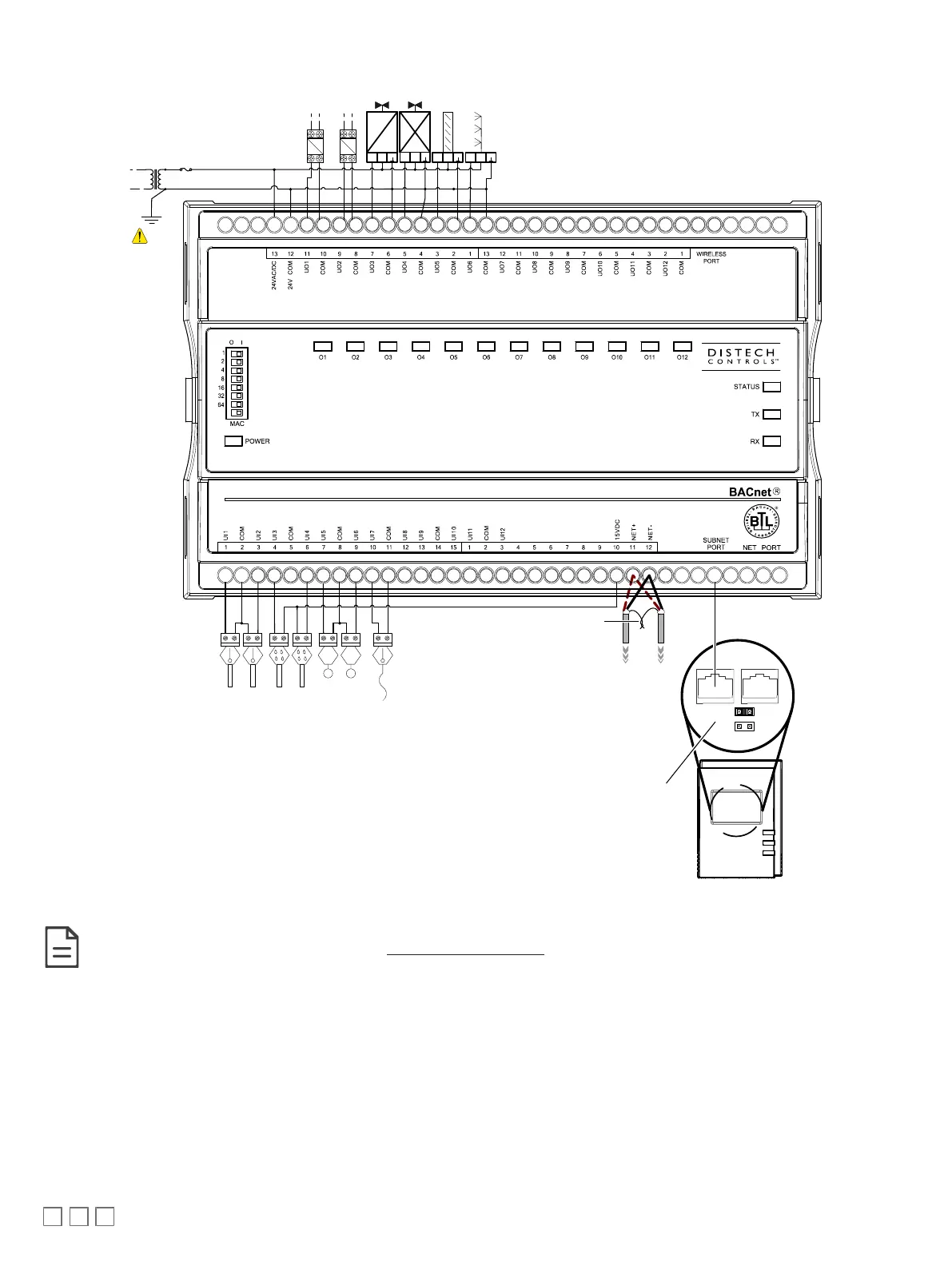
Typical Air Handling Unit Application Wiring Diagram
CoolHeat
Return Air Temperature
10kΩ type II
Supply Air Temperature
10kΩ type II
Mixed Air Temperature
10kΩ type II
Supply Air Humidity
2-wire, 4-20mA
Supply Fan State
Digital contact
Return Fan State
Digital contact
Damper
Return Air Humidity
2-wire, 4-20mA
CT CT
0-10
VDC
~
+
-
0-10
VDC
~
+
-
Humidifier
A2
A1
A2
A1
To
Supply
Fan
Starter
To
Return
Fan
Starter
0-10
VDC
~
+
-
0-10
VDC
~
+
-
Transformer
24VAC
Fuse: 4A Max.
Fast Acting
Electrical
System
Ground
Data Bus Shields: Twist together
and Isolate with electrical tape
From Previous Device
To Next Device
BACnet MS/TP Network
ECB-400
*
* 249 ohm resistor built-in for inputs configured as 0-20mA
Allure EC-Smart-Vue
EOL Enabled at
the last sensor
at the end of
the Bus
ON
EOL
OFF
Back of an Allure
EC-Smart-Vue
Figure16: Typical Power and Network Connections with an Allure EC-Smart-Vue sensor
Although only the Allure EC-Smart-Vue is shown here, any other Allure Series Communicating Sensor can be connected to the subnet port in
this manner. Refer to the sensor’s corresponding Hardware Installation Guide for more details.