Do you have a question about the Ditch Witch JT920 and is the answer not in the manual?
Record serial numbers and purchase dates of your equipment in the provided spaces.
Notify your dealer immediately of any malfunction or failure of Ditch Witch equipment.
Always provide model, serial number, and approximate purchase date when requesting support.
Return damaged parts to dealer for inspection and warranty consideration if within the warranty timeframe.
Order genuine Ditch Witch replacement or repair parts to avoid voiding warranty.
Contact dealer for publications and videos covering safety, operation, service, and repair.
Contact your Ditch Witch dealer for information about on-site, individualized training.
This manual provides safety and operation instructions for your equipment.
Read and keep the manual with the equipment for future reference. Give it to new owners if sold.
Contact your Ditch Witch dealer or visit www.ditchwitch.com for replacement copies.
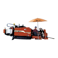
Description of the JT920 directional drilling unit, its features, and compatibility.
Description of the JT920L directional drilling unit, its features, and compatibility.
Diagram and list of controls on the setup console.
Descriptions for main setup controls: Throttle, Track Width, Stabilizer Lift, Frame Tilt, Track Controls.
Descriptions for Autobore Select, Ignition, and Cold Start Switches.
Diagram and list of controls for the drill unit.
Descriptions for Fluid Pump, Spindle, Pipe Lift, Pipe Shuttle, and Autoload controls.
Descriptions for Auxiliary Wrench, Fluid Source, Remote Start, Remote Throttle, and Engine Stop controls.
Controls for Fluid Flow and Fluid Pressure Gauge.
Diagram and list of gauges and indicators on the console.
Descriptions for Air Filter, Fuel, Voltmeter, Engine Temp, Oil Sight Glass, Hourmeter, and Oil Filter/Temp indicators.
Diagram and list of controls for the anchoring system console.
Descriptions for Rotation and Thrust controls, and Anchor Slide Locks.
Diagram and descriptions for ESID display, indicators, and buttons.
Diagram and list of indicators and controls for the Subsite 750 Display.
Descriptions for Readouts (Left/Right, Pitch, Roll, Depth) and Function Buttons.
Follow guidelines on training, utility location, hazard classification, and PPE.
Striking hazards can cause explosion, electrocution, fire, or exposure to materials.
Procedures for emergency shutdown and responding to electric strikes.
Steps for damaged electric/gas lines, fiber optics, and machine fires.
Classifying jobsites and applying precautions for hazards like silica dust.
Explanation of DANGER, WARNING, CAUTION, NOTICE, and IMPORTANT alerts.
Covers turning shafts, electric shock, gases, tools, hazards, crushing weight, moving parts.
Covers explosions, procedures, fiber optics, fluid, traffic, and coolant.
Covers flying objects, hot parts, noise, falls, battery acid, and chemicals.
Review jobsite information, blueprints, and plans before starting.
Inspect jobsite for grade, elevation changes, obstacles, utilities, traffic, and access.
Identify safety hazards and classify the jobsite. Follow safety notices.
Plan the bore path from entry to end, marking it on the ground or paper.
Details on JT920 and JT920L pipe bend limits to prevent damage.
How entry pitch, setback, and depth determine bore path and minimum depth.
Lists of necessary supplies and equipment checks.
Mark bore path, prepare entry point, and follow safety warnings.
Machine is not configured for lifting; use appropriate containers or platforms.
How to properly tie down the unit using identified tiedown points.
Instructions for loading and unloading onto a trailer.
Guidelines for towing when necessary, including speed and force limits.
Procedure to disengage and engage track hydraulics for towing.
Drive unit off trailer following TRANSPORTATION directions.
Start engine, select position, tilt frame, and lower stabilizers.
Proper setup, testing, and use of the electric strike system.
Procedures for testing the ESID and strike system functionality.
Procedures for driving and securing anchors.
Selecting nozzle/bit, scribe line technique, and attaching EZ-Connect.
Steps for loading, connecting, and tightening drill pipe joints.
Basic startup procedures and safety warnings.
Explanation of the eight positions of the thrust/rotation control.
Using manual pipeloader controls or autoload function to add pipe.
Basic procedures for tracking progress and making direction corrections.
Guiding the drill head to the target pit or through the surface.
Procedures and tips for backreaming, including safety.
Calculating the minimum fluid needed for backreaming based on bore size and material.
Procedure for removing anchors from the ground.
Rinsing equipment and disconnecting hoses/cables.
Ensure all wrenches, bits, and devices are loaded on the trailer.
Identifies lubricants (MPG, DEO, MPL, THF, TJC) and their uses.
Table detailing lubrication points, tasks, hours, and lubricants.
Procedures for checking and changing engine oil.
Procedures for checking and changing hydraulic oil and filter.
Lubricating the rotation gearbox and water swivel.
Lubricating the thrust chain and flange bearings.
Lubricating the pipe loader shuttle slide.
Instructions for using and changing cartridges in the pipe auto lubricator.
Checking and refilling the drilling fluid pump crankcase oil.
Table of maintenance tasks by hours (10, 50, 250, 1000, as needed).
Inspection of hoses, battery, alternator belt, and saver sub.
Tips for battery care and checking alternator belt tension.
Procedures for removing saver sub and checking pipe loader inserts.
Cleaning radiator, checking coolant, and changing air/fuel filters.
Checking thrust chain tension and track tension/condition.
Checking proximity switches and photoelectric eyes.
Hand-lubricating threads, cleaning inside pipe, and cleaning threads.
Guide to identifying and resolving strike system problems and error codes.
Procedures for testing voltage and current sensors using the simulator.
Dimensions, operating weight, drill pipe specs, operational data, and engine details.
Hydraulic system, fluid capacities, and battery specifications.
Dimensions, operating weight, drill pipe specs, operational data, and engine details.
Hydraulic system, fluid capacities, and battery specifications.
Recommended bend limits for JT920 drill pipes to prevent damage.
Charts detailing forward and lateral dimensions for bends.
Recommended bend limits for JT920L drill pipes to prevent damage.
Charts detailing forward and lateral dimensions for bends.
How these factors work together to determine bore path.
Determining minimum fluid needed for backreaming based on bore size and material.
Charts showing flow rates for different nozzle sizes and pressures.
Details Major Component and Product Limited Warranties.
Covers frames, gearboxes, pumps, motors, and other major components.
Covers products for 90 days, with specific terms for ground contact parts.
Exclusions include transportation, misuse, abuse, and parts subject to ground contact.
| Brand | Ditch Witch |
|---|---|
| Model | JT920 |
| Category | Farm Equipment |
| Language | English |