6
IP1812EN • 2012-07-10
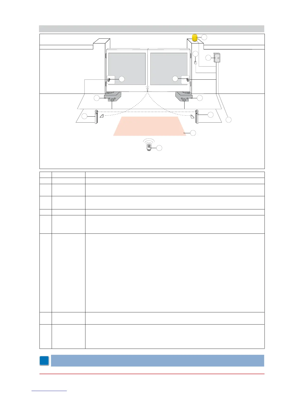
4. STANDARD INSTALLATION
Ref. Code Description
1 GOL4 Transmitter
2 LAMPH
LAMP
Flashing light 24 V=
Flashing light 230 V~
3 XEL5
GOL4M
Key selector
Codied via radio control keyboard
4 LAB9 Magnetic loop detection device for trafc monitoring
5 E2
LOGICM
VIVAH
Control panel
6
CUBIC6
CUBIC6H
CUBIC6C
CUBIC6CG
CUBIC6CY
CUBIC6L
CUBIC6LG
CUBIC6TC
CUBIC6TIG
CUBIC6SBL
CUBIC6SBD
CUBIC6FM
CUBIC6FMTI
Geared motor 230 V~
Geared motor 24 V=
Foundation casing
Oversize foundation casing
Stainless steel foundation casing
Lever mechanism kit
Oversize lever mechanism kit
Chain-operated lever mechanism kit
Oversize gear-operated lever mechanism kit
Lever-operated release kit
Key-operated release kit
Magnetic limit switch kit
Magnetic limit switch kit for lever mechanism
7 XEL2
LAB4
Photocells
Photocells IP55
A Connect the power supply to an approved omnipolar switch with an opening distance
of the contacts of at least 3mm (not supplied).
The connection to the mains must be made via an independent channel, separated
from the connections to command and safety devices.
NOTE: the given operating and performance features can only be guaranteed with the use of DITEC
accessories and safety devices.
TX - 4x0.5 mm²
TX - 4x0.5 mm²
RX - 4x0.5 mm²
RX - 4x0.5 mm²
4x0.5 mm²
*
* 3x0,75 mm² + 1x1,5 mm² [CUBIC6]
2x1,5 mm² [CUBIC6H]
*
3x1.5 mm²
1
7
7
3
2
5
6
2x1.5 mm²
7
7
6
4
A
 Loading...