29
IP1812EN
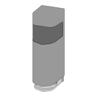
6.8 CUBIC6FM installation
It is possible to limit the travel of the wing by means of magnetic limit switches.
Choose and install the magnetic limit switches as indicated in the relative manual.
Make the electrical connections as shown in the control panel.
WARNING: the magnetic limit switches cannot interrupt the power supply to the motor.
7. Electrical connections
Before connecting the power supply, make sure the plate data correspond to that of the mains
power supply.
An omnipolar disconnection switch with minimum contact gaps of 3 mm must be included in the
mains supply.
Check that upstream of the electrical installation there is an adequate residual current circuit
breaker and a suitable overcurrent cutout.
In the CUBIC6 gearmotors, the blue wire corresponds to the common contact of the motor phases,
and must be connected to the W or Z terminals of the control panel.
The CUBIC6 gearmotor can be connected to the LCA70 and LCA80 control panels.
The CUBIC6H and CUBIC6VH gearmotors can be connected to the LCU40H-HJ control panel.
The electrical connections and the start-up of the gearmotors are shown in the installation manu-
als of the LCA70, LCA80 and LCU40H-HJ control panels.
WARNING:
the electrical connections for the extension of the motor cables must be
made on the outside of the foundation casing in an appropriate junction box (not supplied).