25
IP1812EN
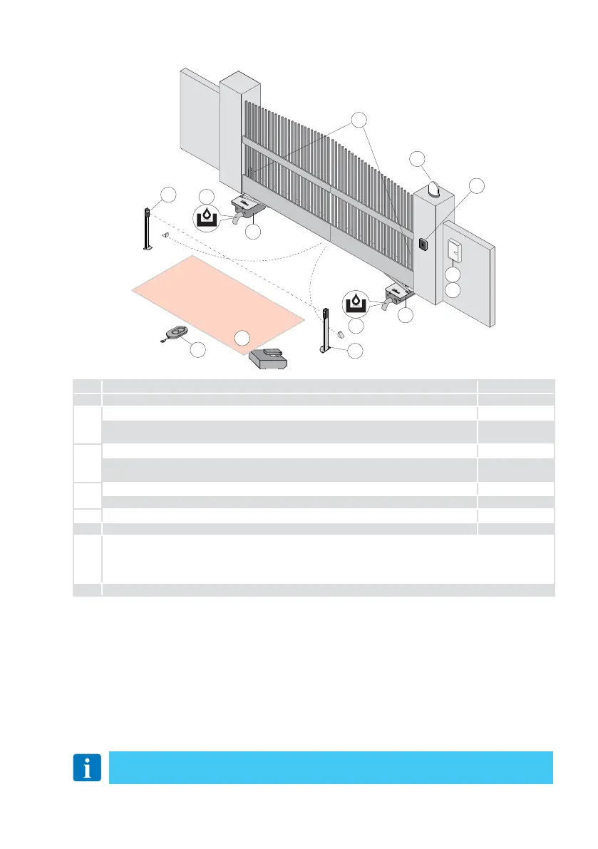
4. Standard installation
NOTE: the given operating and performance features can only be guaranteed with the
use of DITEC accessories and safety devices.
Ref. Description Cable
1 Transmitter /
2
Flashing light 2 x 1,5 mm²
(integrated into the flashing light) - coaxial
antenna 58 Ω
(max 10 m)
3
Key selector switch 4 x 0,5 mm²
Digital combination wireless keypad
*only if an external power supply is used as an alternative to the battery
2 x 0,5 mm² *
4
CUBIC6 4G x 1,5 mm²
CUBIC6 with magnetic limit switches 6G x 1,5 mm²
5 Photocells 4 x 0,5 mm²
6 Control panel 3G x 1,5 mm²
A
Connect the power supply to a type-approved omnipolar switch, with a contact opening distance of at
least 3 mm (not supplied).
The connection to the mains must follow an independent path, separate from the connections to the
control and safety devices
B Connect the drainage pipe to the foundation box.
7
1
7
6
B
B
6
7
2
3
4
5
A