5
IP1854EN - 2013-03-01
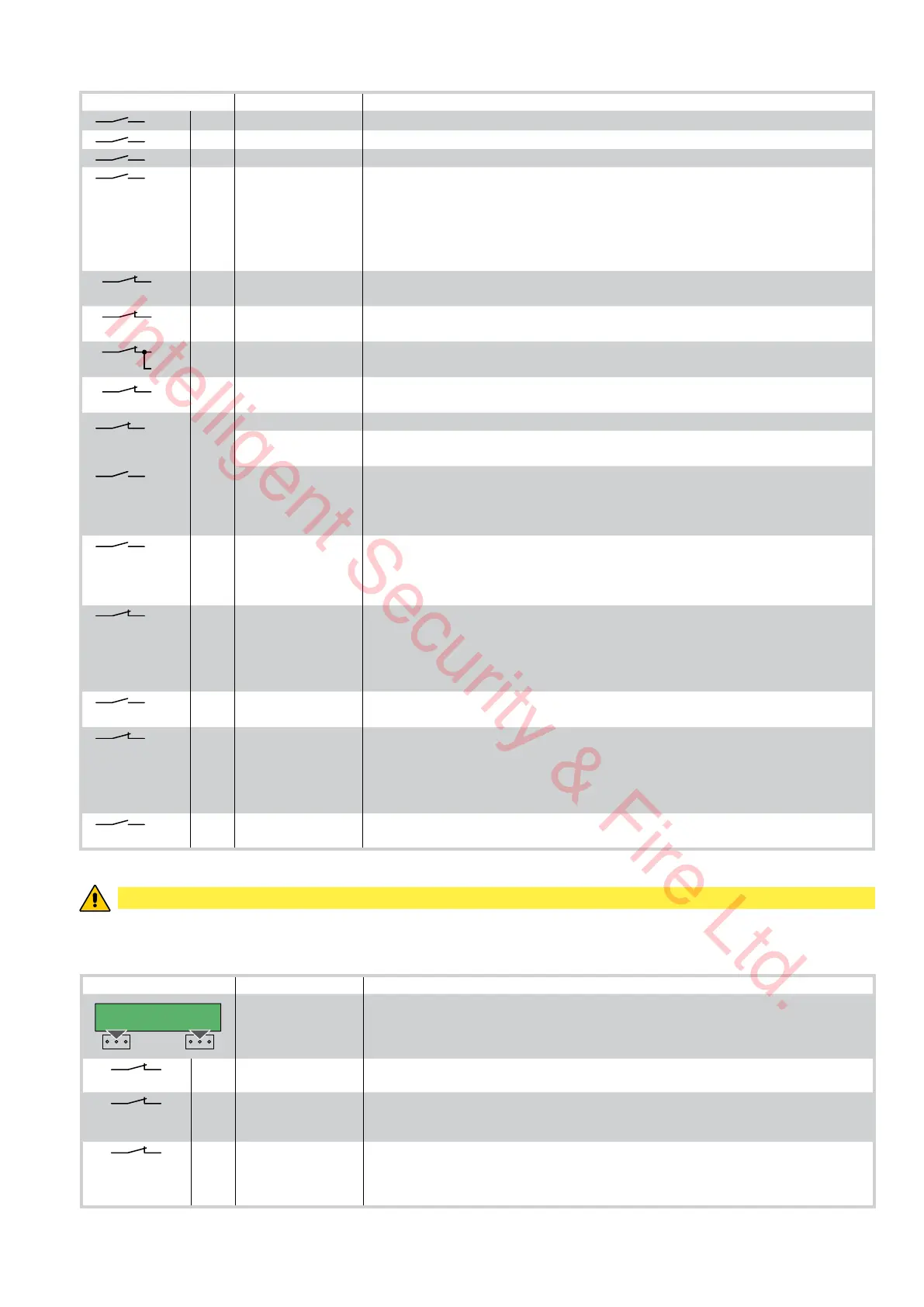
4. Commands
Command Function Description
1
2 N.O. AUTOMATIC CLOSING Permanently closing the contact enables automatic closing.
1
3 N.O. OPENING The opening operation starts when the contact is closed.
1
4 N.O. CLOSING The closing operation starts when the contact is closed.
1
5 N.O. STEP-BY-STEP With D5=ON closing the contact starts a sequential opening or closing operation: open-stop-
close-open.
With D5=OFF closing the contact starts a sequential opening or closing operation: open-stop-
close-stop-open.
Note: if automatic closing is enabled, with S5=ON the stop is not permanent but at a time that
is set by the TC, with S5=OFF the stop is permanent.
41
6
N.C. OPENING SAFETY
DEVICE
Opening the safety contact stops the current opening operation in progress and impedes any
future opening operations.
41
7
N.C. CLOSING SAFETY
DEVICE
Opening the safety contact stops the current closing operation in progress and impedes any
future closing operations.
41
6
7
N.C. SAFETY STOP Opening the safety contact stops and prevents any movement.
Note: it does not carry out the disengagement operation. Use with photocells installed only.
41
8 N.C. REVERSAL SAFETY
DEVICE
Opening the safety contact triggers a reversal of motion (re-opening) during a closing opera-
tion.
1
9 N.C. STOP Opening the safety contact stops the current operation.
EMERGENCY STOP To enable the emergency stop function (e.g. with a specific red button), connect the opening
and closing controls to terminal 9 instead of 1 (9-3, 9-4, 9-20).
1
9 N.O. HOLD-TO-RUN
FUNCTION
Permanently opening the safety contact enables the operator presence dependent function.
In this state, the opening (1-3, 1-20) and closing (1-4) controls function only if held in the pres-
sed position and the automation stops when the controls are released.
All safety switches, the step-by-step control and the automatic closing function are disabled.
1
20 PARTIAL OPENING Closing the contact activates a partial opening operation of the door wing powered by motor 1,
of the duration set with the RP trimmer.
Once the automation stops, the partial opening control performs the opposite operation to the
one performed before stoppage.
0
11
N.C. M2 LIMIT SWITCH With TC=MAX, the limit switch contact opening stops closing movement of motor 2 (M2).
With OM=OFF (1 motor mode) and DIP2=OFF, the limit switch stops closing movement of motor
1 (M1).
With OM=OFF (1 motor mode) and DIP2=ON, the limit switch stops opening movement of motor
1 (M1).
0
11 N.O. M2 PROXIMITY
LIMIT SWITCH
See Chapters 9-10, example 4.
0
12 N.C. M1 LIMIT SWITCH With TC=MAX, the limit switch contact opening stops closing movement of motor 1 (M1).
With OM=OFF (1 motor mode) and DIP2=OFF, the limit switch stops opening movement of
motor 1 (M1).
With OM=OFF (1 motor mode) and DIP2=ON, the limit switch stops closing movement of motor
1 (M1).
0
12 N.O. M1 PROXIMITY
LIMIT SWITCH
See Chapters 9-10, example 4.
WARNING: Make a jumper on all N.C. contacts if not in use. The terminals with the same number are equal.
4.1 Self-controlled safety edge SOFA1-SOFA2 or GOPAVRS
Command Function Description
GOPAV
SOFA1-SOFA2
SAFETY TEST Place the SOFA1-SOFA2 or GOPAVRS device into its housing for plug-in cards AUX.
Connecting terminal 41 enables a safety edge test cycle before every operation.
If the test fails the SA led flashes and the test is repeated.
1
6 N.C. OPENING SAFETY
DEVICE
Connect the output contact of device SOFA1-SOFA2 to terminals 1-6 on the control panel (in
series with the photocell output contact, if installed).
1
7 N.C. CLOSING SAFETY
DEVICE
Connect the output contact of device SOFA1-SOFA2 to terminals 1-7 on the control panel (in
series with the photocell output contact, if installed).
1
8 N.C. REVERSAL SAFETY
DEVICE
Connect the output contact of device SOFA1-SOFA2 to terminals 1-8 on the control panel (in
series with the photocell output contact, if installed).
ATTENTION: for quick operation on the safety edge, connect it to contact 1-6 or to contact 1-7.
Intelligent Security & Fire Ltd.
 Loading...