13
IP1854EN - 2013-03-01
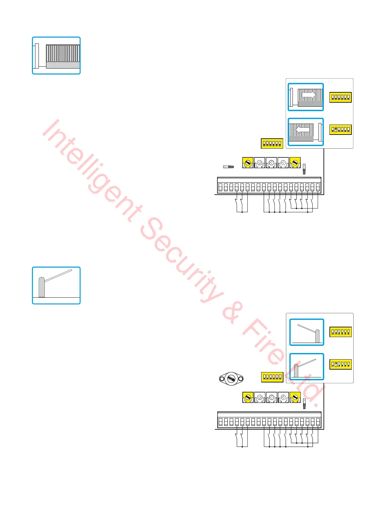
11. Example application for sliding gate
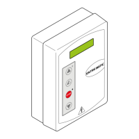
12. Example application for barriers
When using the LOGICM control panel for sliding automation appli-
cations:
- set OM=OFF
- set JR6=OFF
- set TM=MAX
Connect the opening and closing limit switch NC contacts to terminals
0-11-12.
With this configuration, the door wing stops when the limit switches
are activated.
In the event of obstacle detection while opening, the door wing stops,
performing a disengagement operation, whereas during a closing
operation, the door wing reopens.
Select the correct opening direction with DIP2.
• In the event of automation with right-side opening seen from the
automation side (DIP2=OFF), connect the opening limit switch to
terminals 0-12 and closing limit switch to terminals 0-11.
• In the event of automation with left-side opening seen from the
automation side (DIP2=ON), connect the opening limit switch to
terminals 0-11 and the closing limit switch to terminals 0-12.
When using the LOGICM control panel for barrier applications:
- set OM=OFF
- set RF=5 (MAX)
- set TM=MAX
Select the correct opening direction with DIP2.
• In the event of automation with right-side opening seen from the
automation side (DIP2=OFF), connect the opening limit switch to
terminals 0-12 and closing limit switch to terminals 0-11.
• In the event of automation with left-side opening seen from the
automation side (DIP2=ON), connect the opening limit switch to
terminals 0-11 and the closing limit switch to terminals 0-12.
TM TC RP TR R1
15 14 13 12 11 00112345678920 41
Limit switch
Limit switch
OM=OFF
JR6=OFF
1
ON
23456
DIP2=OFF
DIP2=ON
1
ON
23456
1
ON
23456
=MAX <MAX
TM TC RP TR R1
15 14 13 12 11 00112345678920 41
Limit switch
Limit switch
OM=OFF
1
ON
23456
DIP2=OFF
DIP2=ON
1
ON
23456
1
ON
23456
1
5
4
3
2
=MAX <MAX
Intelligent Security & Fire Ltd.