
N
Nicholas DavisAug 4, 2025
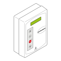
What to do if DITEC 52E shows 'Current limit exceeded'?
- SsreyesAug 4, 2025
If your DITEC Control Panel displays a 'Current limit exceeded' error, it means the motor needs more torque than is available. Try reducing the opening speed. Also, verify that the power supply and its wiring are working correctly.