- 23 -
0DT866 2016-01-25
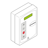
P5
P3 P4P1 P2
41 40 20 9 8 4 3 2 1 1 0 LAMP1 11 12 13
ON
OFF
1 2 3 4 5 6 7 8
DL
2
3
4 5
6 7
DL
M7
M4A
M5
M6
M3
BACK
M4
1 IN NC C NO
M2
J4
15
S3 S4
S5 S2
SAFETY OPEN
F2F1
230 V
GND
L N
+F -F U V W
ON
5. TROUBLESHOOTING
Display message Problem Check
Current limit exceeded Requested motor torque
exceeds available torque.
• Reduce opening speed.
• Check power supply.
• Check power supply wiring.
Insert brake resistance Voltage on BUS exceeds
threshold
• For Sector Reset doors, connect the brake resistance
and set the item on the advanced menu to "YES".
• Switch off the control panel, wait 3 minutes and
reconnect the power supply.
• If the error reoccurs, check that the voltage on the
BUS is lower than 360 V.
Max. BUS voltage BUS voltage exceeds threshold • Switch off the control panel, wait 3 minutes and
reconnect the power supply.
• Check the control panel power supply voltage.
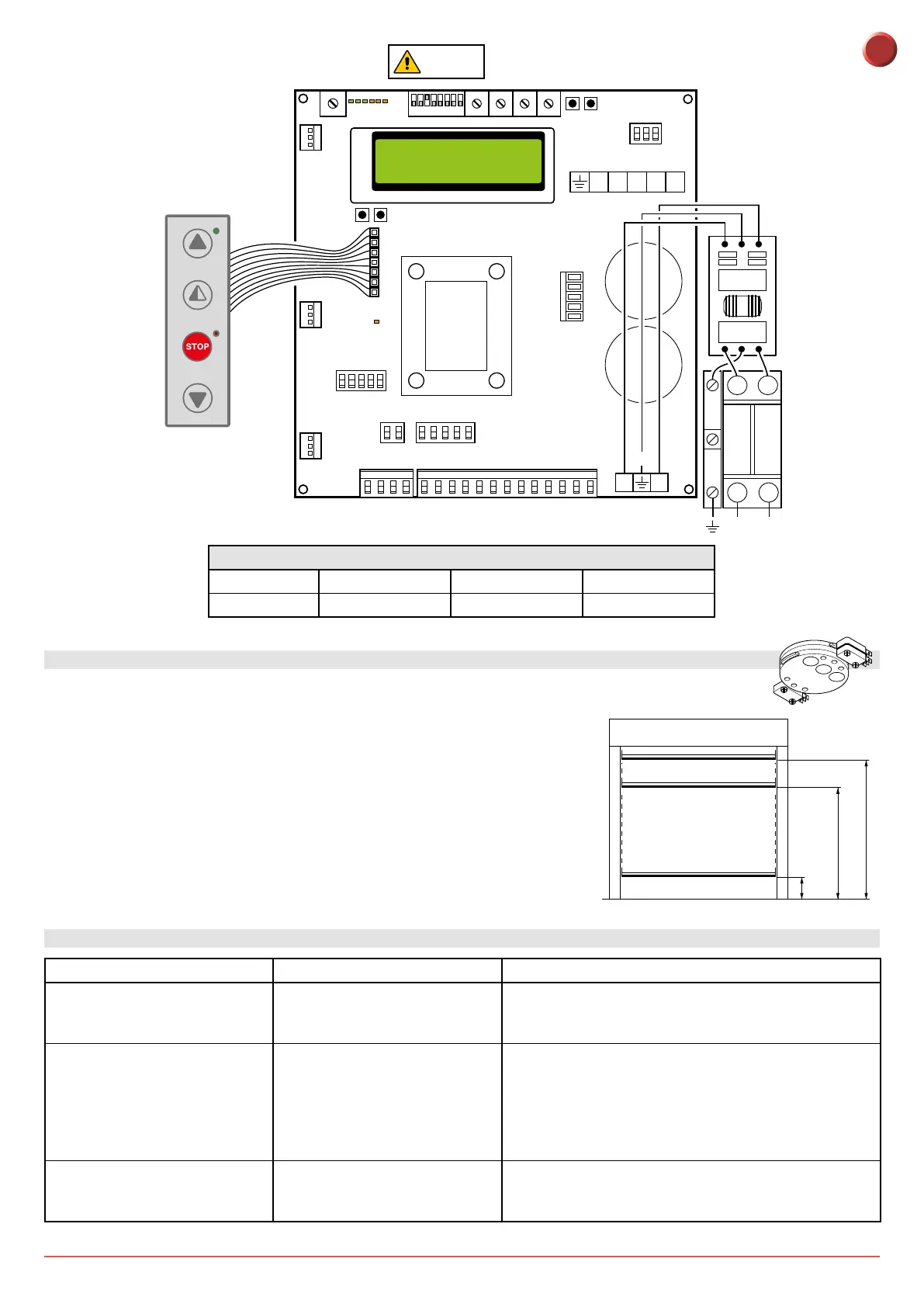
4. LIMIT SWITCH ADJUSTMENT
1. Set the deceleration ramps at zero (P3 - P4)
2. Set the limit switch (C) on the gearmotor so that the door stops about
200/300mm from its closure point.
3. Set the opening limit switch (A) at the opening point.
4. Set the deceleration limit switch (B) so it is triggered at about ¾ of the
opening stroke.
5. Set the opening and closure speeds using trimmers (P1) and (P2) respectively.
6. Set the trimmers of the deceleration ramps - (P3) for opening and (P4) for
closure - to ensure the door stops at its actual "open" and "closed" positions.
C
B
A
B
C
300
A
¾
Dip 3 ON
FUSES
ID Value Size Circuit
F1 - F2 12A - 500V 10.3 x 38 Single phase line
EN