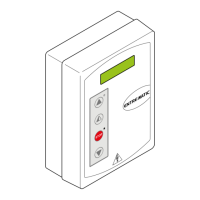
EasyManua.ls Logo

DITEC LCA70 User Manual

DITEC LCA70
40 pages
To Next Page IconTo Next Page
Page #1 background imageLoading...
Page #1 background image
UWV X Z 0 1 6 841
Y
3013
30 5 20
UP
F1
F2
DOWNENTERESC
Passo-passo
Apertura parziale
~LK
LN
COM
JR1
AUX1
R
X
R
A
D
I
O
Antenna
Elettroser
ratura
12 V~ 15 W max
SCHEDA AD INNESTO
Alimentazione
230 V~
50 Hz
24 V~
230 V~ 25 W max
F5A
T3.15A
~
LP
Lampeggiante
Lampada stato
automazione
-
+
FUSE
Uscita 24V 0,3A max
Arresto di sicurezza
Test sicurezze
Sicurezza in chiusura
FUSE
COM
M1
1~
M2
1~
COM
Ditec LCA70
Control panel installation manual for automations with
one or two 230V~ motors
(translation of the original instructions)
IP2368EN • 2020-07-10
www.ditecentrematic.com
Power supply
230 Vac
50 Hz
Flashing light
230V ~ 25W max
STEP-BY-STEP
24V output
partial aperture
SAFETY STOP
Closing safety device
Safety devices test
Electric lock
12 V~ 15 W max
Automation status
lamp output
ANTENNA
PLUG-IN BOARD

Table of Contents

Questions and Answers:

DITEC LCA70 Specifications

General IconGeneral
Motor Voltage24 Vdc
Display7" TFT LCD
Resolution800 x 480 pixels
Operating SystemLinux
ProcessorARM Cortex-A8
Memory256MB RAM
Communication PortsEthernet, USB, RS485

Summary

General Safety Precautions

Safety Functions

Details the safety functions of the control panel, including obstacle recognition with force limiting.

EC Declaration of Conformity

Formal declaration of the control panel's compliance with EC directives for safety and EMC.

Installation and Electrical Connections

Applications

Outlines the intended applications for the Ditec LCA70 control panel in gate automation.

Standard Installation

Describes the standard installation process, including mounting and connections.

Installation Wiring Diagram

Presents the detailed wiring diagram for the control panel's standard installation connections.

Control Inputs, Outputs, and Accessories

Commands and Safety Devices

Details command inputs and safety device connections for automation control and safety.

Command Inputs

Details various command inputs and their functions for controlling the automation's operation.

Safety Inputs

Information on connecting and configuring safety inputs for enhanced protection.

Outputs and Accessories

Describes the control panel's outputs, power supplies, and compatible accessories.

Jumper Settings

Jumper Setting

Explains the function and setting of the JR1 jumper for display mode selection.

Application Examples

Automations with Two Swinging Gates

Wiring examples for two-leaf swinging gate automations.

Automations with One Swinging Gate Wing

Wiring examples for single-leaf swinging gate automations.

Using Menus and Configuration

Menu Navigation and Display

Details how to navigate menus, switch display on/off, and use navigation keys.

Menu Map

A comprehensive map illustrating the control panel's menu structure and parameters.

Product Setup and First Use

WZ Configuration Wizard

Guide to accessing and using the quick configuration wizard for initial product setup.

Start-up Examples and Sequences

Provides a basic start-up example and frequently used menu sequences for setup.

Control Panel Configuration and Settings

Main Menu Overview

An overview of the primary menu categories for control panel settings and configurations.

Automatic Configuration (AT Menu)

Detailed parameters and settings within the Automatic Configuration (AT) menu.

Basic Settings & Adjustments (BC & BA Menus)

Covers BC basic settings and BA basic adjustments for core operation.

Radio Operations, Special Functions, Cycles Counter, and Advanced Parameters

Details RO radio operations, SF special functions, CC cycles counter, and AP advanced parameters.

Diagnostics

Data Logging Overview

Information on the control panel's integrated data logging capabilities for alarms.

Alarm Counter

View recorded alarms and the number of times each has been triggered.

Alarm Log

View the log of the last twenty recorded alarms for troubleshooting.

Display Signals

Display of Automation Status

Visualisation of the automation's current status on the control panel display.

Display of Safety Devices and Commands

Display codes for safety devices and commands for system monitoring.

Visualisation of Alarms and Faults

How to interpret and view alarms and fault messages on the control panel display.

Troubleshooting

Control Panel Issues

Troubleshooting steps for issues like no power, blown fuses, or short-circuited accessories.

Automation Operation Issues

Solutions for problems with automation opening/closing, safety devices, or automatic closure.

Remote Control Issues

Guidance for troubleshooting remote control range limitations and operational failures.

Related product manuals