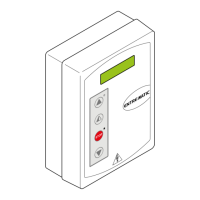
The Ditec LOGICM is a control panel designed for 230 V~ automation systems, capable of managing one or two motors. This device is suitable for various applications, including two-motor swing gates, one-motor swing gates, sliding gates, and barriers, offering a comprehensive solution for automated access control.
Function Description
The LOGICM control panel provides a wide range of functions to manage automated gates and barriers. It supports both automatic closing and manual control options, including opening, closing, and step-by-step operations. The step-by-step function can be configured to follow an open-stop-close-open or open-stop-close-stop-open sequence, depending on the DIP switch settings. This flexibility allows users to tailor the gate's operation to specific needs.
Safety is a primary concern, and the LOGICM integrates multiple safety features. It includes inputs for opening, closing, and reversal safety devices, which can stop or reverse the gate's movement upon detection of an obstacle. An emergency stop function is also available, allowing immediate cessation of all operations. For enhanced safety, the panel supports a "hold-to-run" function, where the gate only moves as long as the control button is pressed, disabling automatic closing and other safety switches for specific scenarios.
The panel can manage partial opening operations, allowing one gate wing to open partially for pedestrian access, with the duration set by a dedicated trimmer. It also supports limit switches for precise control over the gate's opening and closing movements, ensuring the gate stops at the desired positions. Both normally closed (N.C.) and normally open (N.O.) limit switches are supported, offering versatility in installation.
For advanced safety, the LOGICM is compatible with self-controlled safety edges like SOFA1-SOFA2 or GOPAVRS. These devices perform a test cycle before each operation, and if the test fails, the system indicates an error and repeats the test, ensuring the safety edge is always functional.
The control panel provides various outputs for accessories, including a power supply for external devices, an automation status lamp, and lamps indicating open or closed gate status. It can also control flashing lights, electric blocks, and electric motor brakes, enhancing the overall functionality and safety of the automation system. Courtesy lights can be connected to activate for a set period after a command, improving visibility.
The LOGICM supports both single and two-motor configurations. In two-motor systems, it can manage the independent or simultaneous movement of gate wings, with adjustable delays between motors for overlapping or non-overlapping operations. It also includes an electronic antifreeze system to maintain motor function in low ambient temperatures.
Usage Features
The LOGICM control panel offers extensive adjustability through trimmers, DIP switches, and jumpers, allowing for fine-tuning of its operation.
-
Trimmers:
- TM (Operating Time): Sets the total operating time of the gate, from 10 to 120 seconds.
- TR (Motor Delay Time): Adjusts the delay between the start of motor 1 (M1) and motor 2 (M2) during closing and opening operations. This is crucial for managing overlapping gate wings.
- TC (Automatic Closing Time): Configures the delay before the gate automatically closes, from 0 to 120 seconds. This can be triggered after a safety switch activation or after the gate fully opens.
- RF (Power Setting): Adjusts the voltage supplied to the motors, influencing their power and speed.
- R1 (Obstacle Thrust): Sets the sensitivity of the obstacle detection system. A lower setting increases sensitivity, causing the gate to stop or reverse more easily upon encountering an obstacle.
- RP (Partial Aperture): Sets the duration of the partial opening operation for motor 1, from 0 to 30 seconds.
-
DIP Switches:
- DIP1 (Radio Mode): Selects between step-by-step operation or direct opening for radio commands.
- DIP2 (Direction Selection): Determines the opening direction (right or left) in one-motor mode.
- DIP3 (Restore Automatic Closing Time): Configures how the automatic closing timer is reset after a safety switch activation.
- DIP4 (Automation Status at Power On): Defines the gate's behavior when power is restored (open or closed).
- DIP5 (Electric Lock Release): Enables or disables the electric lock release function.
- DIP6 (Preflashing): Activates a 3-second preflashing before the gate starts moving, either during opening, or for both opening and closing, especially with automatic closing enabled.
-
Jumpers:
- JR4 (Overtravel Reduction): Reduces the overtravel distance of the gate wing, useful if the gate performs excessive overtravel.
- JR6 (Application Type): Selects the application type, such as sliding gate or other applications.
- NIO (Electronic Antifreeze System): Enables or disables the antifreeze system.
- JR10 (Maximum Power at Start): Allows the motor to start at maximum power for 1 second, providing extra force at the beginning of the movement.
- OM (Automation Type): Configures the panel for one-motor or two-motor automation.
- D5 (Step-by-Step Sequence): Defines the step-by-step sequence (open-stop-close-stop-open or open-stop-close-open).
- S5 (Step-by-Step Sequence Stop Duration): Determines if the stop in the step-by-step sequence is permanent or temporary.
- JT (Closing Operation Time): Sets the closing operation time relative to the TM trimmer.
- EO (Electric Lock Function): Powers the electric lock either continuously when automation is closed or for 1 second at the beginning of the opening operation.
- SO (Reversal Safety Switch Function): Configures how the automation responds to a reversal safety switch, either allowing opening operations or disabling all operations.
The LOGICM also provides LED indicators for power, safety contact status, operation count, and activation of commands/adjustments, aiding in troubleshooting and monitoring.
Maintenance Features
The Ditec LOGICM is designed for reliable operation, but regular checks and proper installation are essential for its longevity and safety.
- Initial Setup and Checks: Before starting up, it's crucial to bridge any unused N.C. safety contacts with jumpers. The application type (one-motor, sliding gate) must be correctly selected, and limit switches, if installed, should be adjusted to trigger near the mechanical end stops. Trimmers for RF and R1 should be set to half, and TM to MAX initially. For overlapping door wings, TR should be set to more than 3 seconds.
- Motor Polarity and Functionality: After initial power-on, the motor polarity should be checked and swapped if the direction of motion is incorrect. It's important to perform opening and closing commands to verify that the automation functions correctly and that limit switches are properly set.
- Safety Device Verification: All safety devices must be connected and their functionality verified by removing the temporary jumpers. This includes photocells and safety edges.
- Obstacle Detection Adjustment: The RF and R1 trimmers should be adjusted to ensure the automation functions correctly while providing adequate safety in case of collision. The system is designed to reopen both door wings if an obstacle is encountered during the closing of the second wing, then proceed with one wing at a time.
- Compliance and Regulations: The forces exerted by the door wings must comply with EN12453-EN12445 regulations.
- Accessory Connection: If a radio receiver is used, it should be connected to the AUX connector, and transmitters programmed according to their manual. All elements must function correctly.
- Plug-in Cards: When installing or removing plug-in cards (e.g., for radio receivers or magnetic loops), the power supply must be disconnected to prevent damage.
- Servicing and Replacement: In case of servicing or replacing the control panel, the entire start-up procedure should be repeated to ensure proper configuration and functionality.
- Troubleshooting: The manual provides a detailed troubleshooting guide to address common issues such as the automation not opening/closing, opening but not closing, or external safety devices not activating. This guide helps identify possible causes (e.g., no power, short-circuited accessories, blown fuse, open safety contacts, faulty limit switches, motor thermal overload) and suggests corresponding remedies.