
J
John RiveraAug 9, 2025
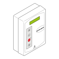
Why doesn't my DITEC Control Panel remote control work?
- SSusan SmithAug 9, 2025
If your DITEC Control Panel remote control isn't working, it could be due to a missing or incorrect storage module. Turn off the automation and plug in the correct storage module. Check that the transmitters are correctly memorized on the built-in radio. If there's a fault with the radio receiver built into the control panel, the remote control code can be read by removing the storage module.