37
IP2251EN
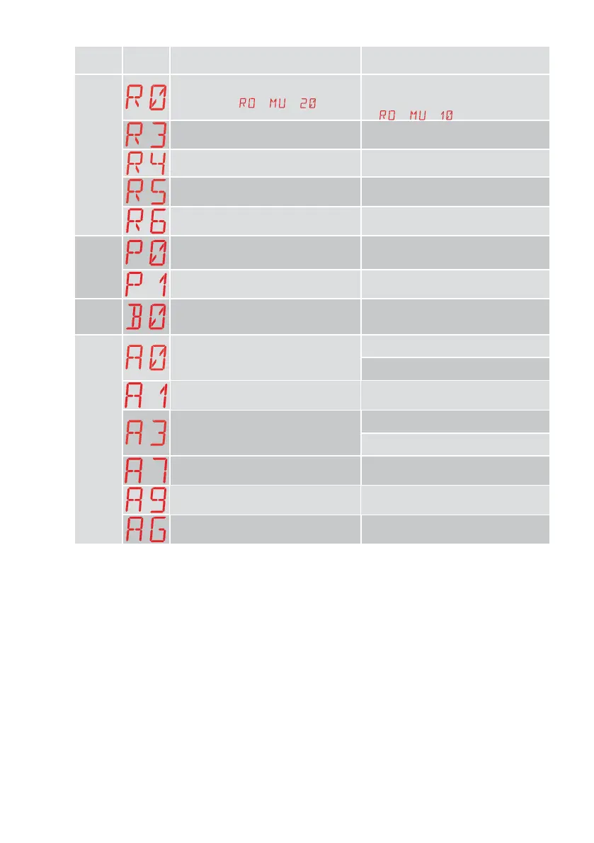
Type of
alarm
Display Description Operation
Radio operations alarm
R0 - Insertion of a storage module contain-
ing over 100 stored remote controls
WARNING: the
→ → setting is
made automatically.
To save the system configurations on the
storage module, delete any stored remote
controls and bring the total to less than 100.
Set
→ → .
R3 - Storage module not detected Insert a storage module.
R4 - Storage module not compatible with
the control panel
Insert a compatible storage module.
R5 - No serial communication with the
storage module
Replace the storage module.
R6 - Insertion of a specific storage module
for testing
Power supply
alarm
P0 - No mains voltage Check the control panel is powered correctly.
Check the line fuse.
Check the mains power supply.
P1 - Microswitch voltage too low Check the control panel is powered correctly.
Battery
alarm
B0 - Battery almost flat Check battery voltage.
Replace battery.
Accessories alarm
A0 - Failure of test of safety sensor on con-
tact 6
Check the device SOFA1-A2 is working
correctly.
If the supplementary SOF board is not
inserted, check the safety test is disabled.
A1 - Simultaneous safety sensor test on
contacts 6 and 8 failed
Check the wiring and correct operation of
the safety sensor.
A3 - Failure of test of safety sensor on con-
tact 8
Check the device SOFA1-A2 is working
correctly.
If the supplementary SOF board is not
inserted, check the safety test is disabled.
A7 - Incorrect connection of contact 9 to
terminal 41
Check that terminal 1 and 9 are correctly
connected.
A9 - Overload on output +LP- Check the device connected to output +LP- is
working properly.
AG - Alarm for short-circuit on output -LK+ Check the device connected to output -LK+
is working properly.