7
IP2368EN
EN
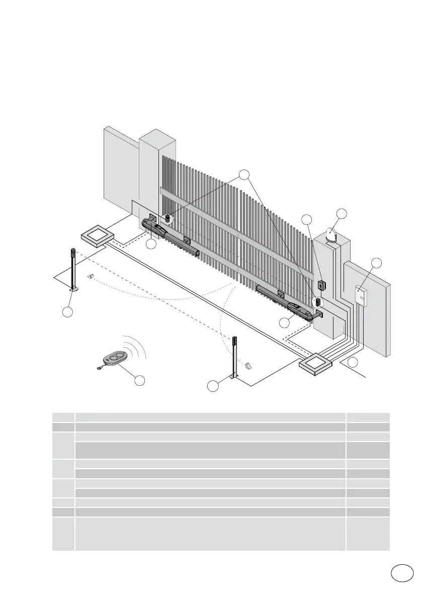
4.2 Standard installation
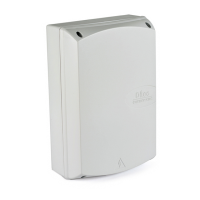
4.1 Maintenance
The control panel doesn't require any special maintenance.
Make regular checks to ensure the seals on the box and the electrical connections are in good
condition.
Ref. Description Cable
1 Transmitter /
2
Flashing light 2 x 1mm²
Antenna (integrated in the flashing light)
RG-58 coax
cable (50Ω)
3
Key selector switch 4 x 0.5mm²
Digital combination wireless keypad /
4
Actuator (motor) 4 x 1.5mm²
Extra low voltage limit switch unit (if present) 3 x 0.5mm²
5 Photocells 4 x 0.5mm²
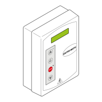
6 Control panel 3G x 1.5mm²
A
Connect the power supply to a certified-compliant omnipolar switch (not included) with
a contact opening distance of at least 3 mm.
Connection to the mains must be via an independent channel, separated from the con-
nections to the command and safety devices.
1
4
6
A
3
2
5
5
4
5