- 26 -
0DT866 2016-01-25
10
Service thresh
to scroll
or
to conrm
CHANGE VALUE
Option available only if YES has been
selected for point 14).
Set value to steps of 1000 cycles Max
200,000 cycles
11
Enable stop 1-2
to scroll
or
to conrm
YES
If set to YES, opening of the contact
1-2 STOPS the door.
NO
12
Brake resistance
(default NO)
to scroll
or
to conrm
YES
Set to YES when the door is supplied
with brake resistance.
NO
13
PARAMETER RESET
to scroll
or
to conrm
CONFIRM
Conrm to go back to the installation
menu.
6.3 Service menu (password required)
The Service menu is used to modify the brake resistance thresholds, the overcurrent threshold
To access the Service menu:
- STOP the door
- Set DIP5 to ON
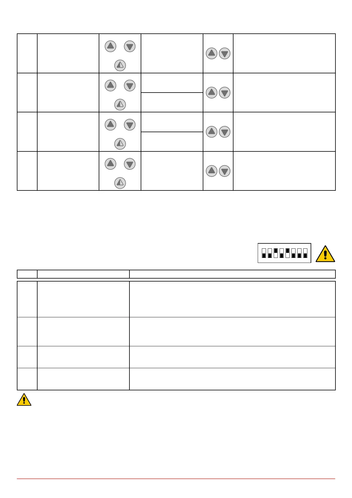
- Enter the PW: button sequence OPEN- OPEN- CLOSE- PARTIAL OPENING
1 2 3 4 5 6 7 8
ON
STEP 1
st
level options Notes
1 MIN BRAKING VOLT.
(Minimum bus voltage)
Default 340V DC
If the BUS voltage falls below this value, a check on the control panel power
supply line is requested (wire section suitable for withstanding the absorbed
current.
When the bus voltage decreases, the bus current increases). Varies from 300V
to 350V
2 MAX BRAKING VOLT.
(Adjustment of brake resistance
intervention threshold)
Default 380V DC
Value above which insertion of brake resistance is required.
Varies from 355V to 400V
3 OVERCURRENT LIMIT
Default 10A
If the current on the BUS exceeds the set threshold, the door opens at half the
speed to reduce absorption.
4 ALARM LIST The last 50 alarms are displayed: Overcurrent; bus voltage exceeds limit,
Intervention of brake resistance, inverter overtemperature, faulty motor driver
(encoder). To exit, press partial opening
ONCE PROGRAMMING HAS ENDED, SET DIP5 TO OFF