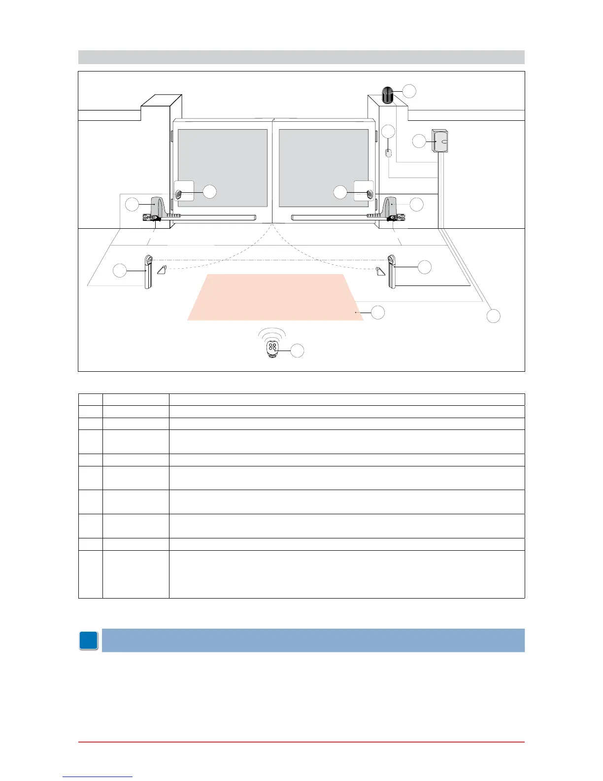
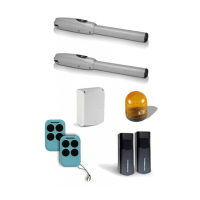
4. STANDARD INSTALLATION
Ref. Code Description
1 GOL4 Transmitter
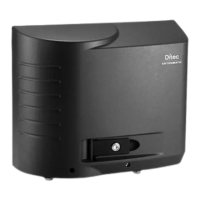
2 LAMPH Flashing light
3 XEL5
GOL4M
Key selector
Codied via radio control keyboard
4 LAB9 Magnetic loop detection device for trafc monitoring
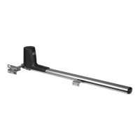
5 OBBI3BH
OBBI3BFCH
Right geared motor
Right geared motor with limit switch
6 OBBI3BH
OBBI3BFCH
Left geared motor
Left geared motor with limit switch
7 XEL2
LAB4
Photocells
Photocells IP55
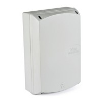
8 E2HOB Control panel
A Connect the power supply to an approved omnipolar switch with an opening distance
of the contacts of at least 3mm (not supplied).
The connection to the mains must be made via an independent channel, separated
from the connections to command and safety devices.
NOTE: the given operating and performance features can only be guaranteed with the use of DITEC
accessories and safety devices.