D I V E R S I T E C H O M - G F C M
4.0 - Preventive Maintenance
1. Injection Cleaning System
Regular checklist:
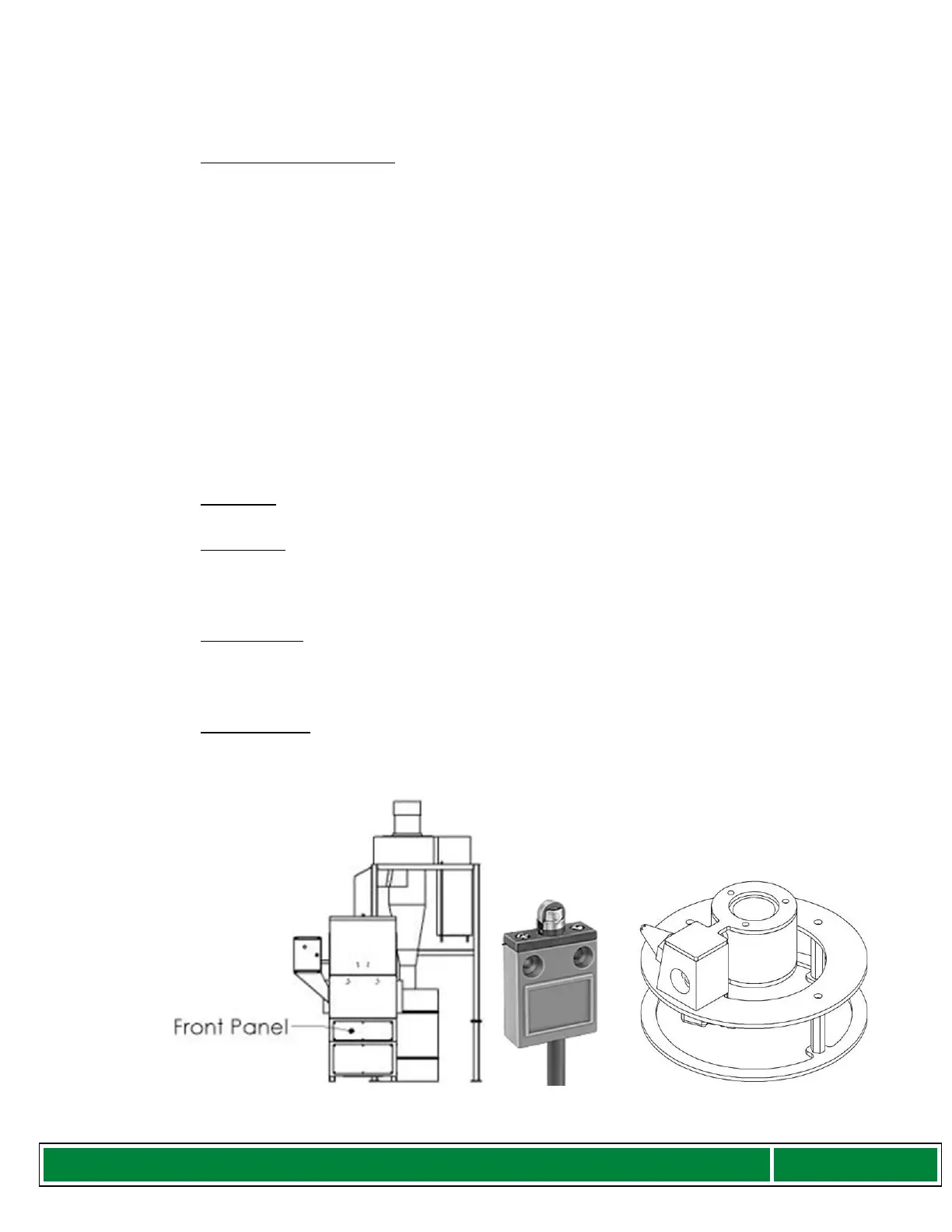
a) Inspect the Limit switch at the bottom of the assembly for any debris
b) Ensure that the Nozzle Assembly disc properly aligns with the Limit switch
to ensure that contact occurs. This can be achieved doing a “Dry Run”.
Step 1: Open the top by releasing both latches.
Step 2: Remove filters/spacers inside the Cabinet.
Step 3: Cut air supply to the unit.
Step 4: There is a Maintenance switch on the side of the Cabinet below
the Control Box, turn this switch on.
Step 5: Once the LCD reads “Ready to Clean”
Step 6: Press the start button
Step 7: Let the unit run up & down.
Once this checklist is verified, please turn OFF the switch on the side of the Cabinet
below the Control Box. This switch is for maintenance only.
2. Hardware
Bolts and nuts should be checked periodically and tightened.
3. Dust Barrel
Empty out the contents of the dust barrel periodically. Please ensure that the
materials are disposed of properly in accordance with local disposal laws.
Important Note: Barrel should not be more than ¾ full.
4. Exhaust Filter
After cleaning filters visually inspect the exhaust filter located behind the cyclone.
Replace the filter when necessary.
Important Note: Do not place Exhaust filter into the machine.
5. Cabinet debris
After every 24 filters cleaned remove panel in front of the Cabinet, inspect and
vacuum (if necessary) around the cleaning mechanism base.
Figure 6: Front Panel, Limit Switch and Nozzle Assembly