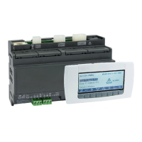
Universal-XR 4/17 UXR01212015_REV1.4mm
Installation and Operating Instructions
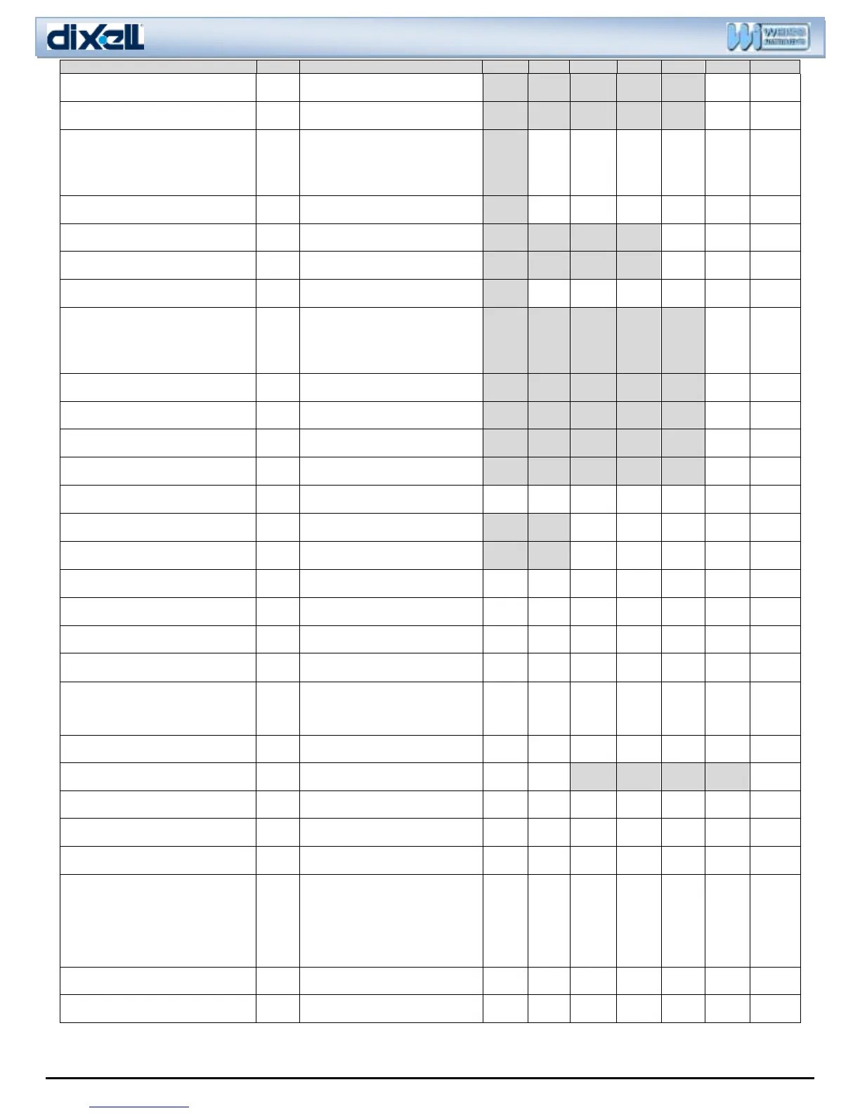
Maximum duration of defrost
(second evaporator)
Defrost termination temperature (second
evaporator)
-55 to 50C;
-67 to 122°F
Rt (0) = Real temp.
it (1) = Temp. at defrost start
sEt (2) = Set Point
dEF (3) = “DEF” label
dEG (4) = “DEG” label
El (0) = Electrical
rE (1) = Hot Gas
First defrost after power on
Y (0) = Immediate
N (1) = After normal interval
Evaporator fan operating mode
C_n (0) =On with Comp, off with defrost
O_n (1) =On regardless of comp, off w/
defrost
C_y (2) =On with comp, on with defrost
O_y (3) =Always on
Evaporator fan stop temperature
-55 to 50C;
-67 to 122°F
Evaporator fan delay after defrost
Thermostat probe calibration
-12.0 to 12.0C;
-21 to 21F
Evaporator probe presence
N (0) = evaporator probe not present
Y (1) = evaporator probe present
Evaporator probe calibration
-12.0 to 12.0C;
-21 to 21F
n (0) = third probe not present,
Y (1) = third probe present.
-12.0 to 12.0C;
-21 to 21F
Y (0) = With decimal point in C only
N (1) = No decimal point
Temperature measurement unit (°C/°F)
C (0) = Celsius
F (1) = Fahrenheit
P1 (0) = Thermostat probe
P2 (1) = Evaporator probe
P3 (2) = Third probe
sEt (3) = SET-POINT
0 to 20min0sec, res. 10sec
Cl (0) = cooling
Ht (1) = heating
Compressor ON time with faulty probe
Compressor OFF time with faulty probe
Alarm muting configuration for
buzzer & relay
n (0) = Mute buzzer only
Y (1) = Mute buzzer & relay
Second Digital input configuration
dEF(0) = Start defrost
dor (1) = Door switch
AUS (2) = Auxiliary relay
ES (3) = Energy saving
onF (4) = Remote On/OFF
EAl (5) = Generic alarm
bAl (6) = Serious alarm
Second Digital input polarity
Cl (0) = Closed circuit
oP (1) = Open circuit

 Loading...