,QVWDOOLQJDQG2SHUDWLQJ,QVWUXFWLRQV
Digital controller with off cycle defrost
XR20C
CONTENTS
1. GENERAL WARNING___________________________________________ 1
2. GENERAL DESCRIPTION _______________________________________ 1
3. CONTROLLING LOADS _________________________________________ 1
4. FRONT PANEL COMMANDS_____________________________________ 1
5. TEMPERATURE ALARM AND ITS DURATION RECORDING (HACCP)___ 1
6. MAIN FUNCTIONS _____________________________________________ 1
7. PARAMETERS ________________________________________________ 2
8. DIGITAL INPUT________________________________________________ 2
9. INSTALLATION AND MOUNTING _________________________________ 3
10. ELECTRICAL CONNECTIONS ___________________________________ 3
11. HOW TO USE THE HOT KEY ____________________________________ 3
12. ALARM SIGNALS ______________________________________________ 3
13. TECHNICAL DATA _____________________________________________ 3
14. CONNECTIONS _______________________________________________ 3
15. DEFAULT SETTING VALUES ____________________________________ 4
1. GENERAL WARNING
1.1 PLEASE READ BEFORE USING THIS MANUAL
• This manual is part of the product and should be kept near the instrument for
easy and quick reference.
• The instrument shall not be used for purposes different from those described
hereunder. It cannot be used as a safety device.
• Check the application limits before proceeding.
1.2
SAFETY PRECAUTIONS
• Check the supply voltage is correct before connecting the instrument.
• Do not expose to water or moisture: use the controller only within the operating
limits avoiding sudden temperature changes with high atmospheric humidity to
prevent formation of condensation
• Warning: disconnect all electrical connections before any kind of maintenance.
• Fit the probe where it is not accessible by the End User. The instrument must
not be opened.
• In case of failure or faulty operation send the instrument back to the distributor
or to “Dixell s.r.l.” (see address) with a detailed description of the fault.
• Consider the maximum current which can be applied to each relay (see
Technical Data).
• Ensure that the wires for probes, loads and the power supply are separated
and far enough from each other, without crossing or intertwining.
• In case of applications in industrial environments, the use of mains filters (our
mod. FT1) in parallel with inductive loads could be useful.
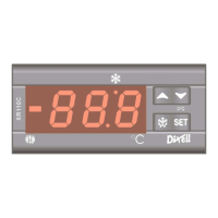
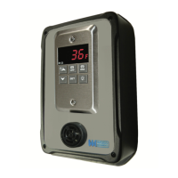
2. GENERAL DESCRIPTION
Model
XR20C
, format 32 x 74 mm, is a digital termostat with off cycle defrost
designed for refrigeration applications at normal temperature. It provides a relay
output to drive the compressor and a PTC or NTC probe input. A internal timer
manages the off cycle defrost. The instrument is fully configurable through special
parameters that can be easily programmed through the keyboard.
3. CONTROLLING LOADS
3.1 COMPRESSOR
The regulation is performed according to the temperature measured by the
thermostat probe with a positive differential from the set point: if the temperature
increases and reaches set point plus differential the compressor is started and then
turned off when the temperature reaches the set point value again.
In case of fault in the thermostat probe the start and stop of the compressor are
timed through parameters “
COn
” and “
COF
”.
3.2 DEFROST
Defrost is performed through a simple stop of the compressor. Parameter “
IdF
”
controls the interval between defrost cycles, while its length is controlled by
parameter “
MdF
”.
4. FRONT PANEL COMMANDS
SET
: To display target set point; in programming mode it selects a parameter or
confirm an operation.
(DEF)
To start a manual defrost
'
'
(UP): To see the last temperature alarm happened; in programming mode it
browses the parameter codes or increases the displayed value.
&
&
(DOWN) To see the last temperature alarm happened; in programming mode it
browses the parameter codes or decreases the displayed value.
KEY COMBINATIONS:
'
'
+
&
&
To lock & unlock the keyboard.
SET +
&
&
To enter in programming mode.
SET +
'
'
To return to the room temperature display.
4.1 USE OF LEDS
Each LED function is described in the following table.
LED MODE FUNCTION
ON Compressor enabled
Flashing
-Programming Phase (flashing with
)
- Anti-short cycle delay enabled
ON Defrost enabled
Flashing
- Programming Phase (flashing with
)
ON An temperature alarm happened
5. TEMPERATURE ALARM AND ITS DURATION
RECORDING (HACCP)
XR20C signals and records temperature alarms, together with their duration and
max value reached. See drawing:
Ex. High temperature alarm
Set
ALu
High temp. alarm
Time
Temperature
ALL
Low temp. alarm
;
;
;
Max
Temperature
5.1 HOW TO SEE THE ALARM DURATION AND MAX (MIN)
TEMPERATURE
If the alarm LED is on, an alarm has taken place.
To see the kind of alarm, the max (min) reached temperature and alarm duration do
as follows:
1. Push the Up or Down key.
2. On the display the following message is shown::
“
HAL
” for high temperature alarm (“
LAL
” fot the minimum allarm), followed by
the
Maximum (minimum) temperature.
Then the “
tiM
” (
tiM
e) message is displayed, followed by the
“Duration”
in
h.mm.
3. Then the instrument displays the temperature once again.
NOTE1:
if an alarm is still occurring the “
tim
” shows the partial duration.
NOTE2:
the alarm is recorded when the temperature come back to normal values
5.2 HOW TO RESET A RECORDED ALARM OR ONE THAT IS
STILL OCCURRING
1. Hold the SET key pressed for more than 3s, while the recorded alarm is
displayed. (the rSt message will be displayed)
2. To confirm the operation, the “rSt” message starts blinking and the normal
temperature will be displayed.
6. MAIN FUNCTIONS
6.1 HOW TO SEE THE SETPOINT
1. Push and immediately release the
SET
key: the display will
show the Set point value;
2. Push and immediately release the
SET
key or wait for 5 seconds to display the
probe value again.
6.2 HOW TO CHANGE THE SETPOINT
1. Push the
SET
key for more than 2 seconds to change the Set point value;
2. The value of the set point will be displayed and the
LED starts blinking;
3. To change the Set value push the
'
'
or
&
&
arrows within 10s.
4. To memorise the new set point value push the
SET
key again or wait 10s.
6.3 HOW TO START A MANUAL DEFROST
Push the
DEF
key for more than 2 seconds and a manual
defrost will start.