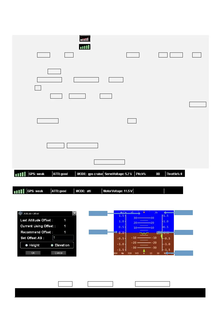
STEP1: Check Signal Strength: shows no communication between GS and MC, please check
Troubleshooting in Appendix. is constructed, can go to next step.
STEP2: Aircraft: When GPS signal is good enough, click Aircraft will show LATI, LONGI and ALTI of
aircraft, then the aircraft logo will be showed on the map; if the aircraft logo can‟t be found, please
double click Aircraft.
STEP3: AltitudeOffSet: Click AltitudeOffSet from Sys_set, you can just use the value recommended, and
click OK. Read the paragraph below to get more details.
STEP4: Switch Height or Elevation Mode: Height mode shows relative height, and the 0 meter is the
aircraft height when you choose Height mode, above 0 is positive and below 0 is negative. Elevation
mode shows height above sea level, figure is showed in Fig②
STEP5: Home Point: Home point can be found only when GPS signal is good enough. If WKM, Home
Point is 20 meters above the aircraft position where user pushes the throttle stick first time; while ACE is
30 meters.
STEP6: View Fly Trace, Instrument Board and State Information: For displaying flight track and aircraft
state. Contents are decided by autopilot system. Fig①A will be displayed if you are using WKM; Fig①B
will be displayed if you are using ACE. Instrument Board is showed in Fig③.



 To Next Page