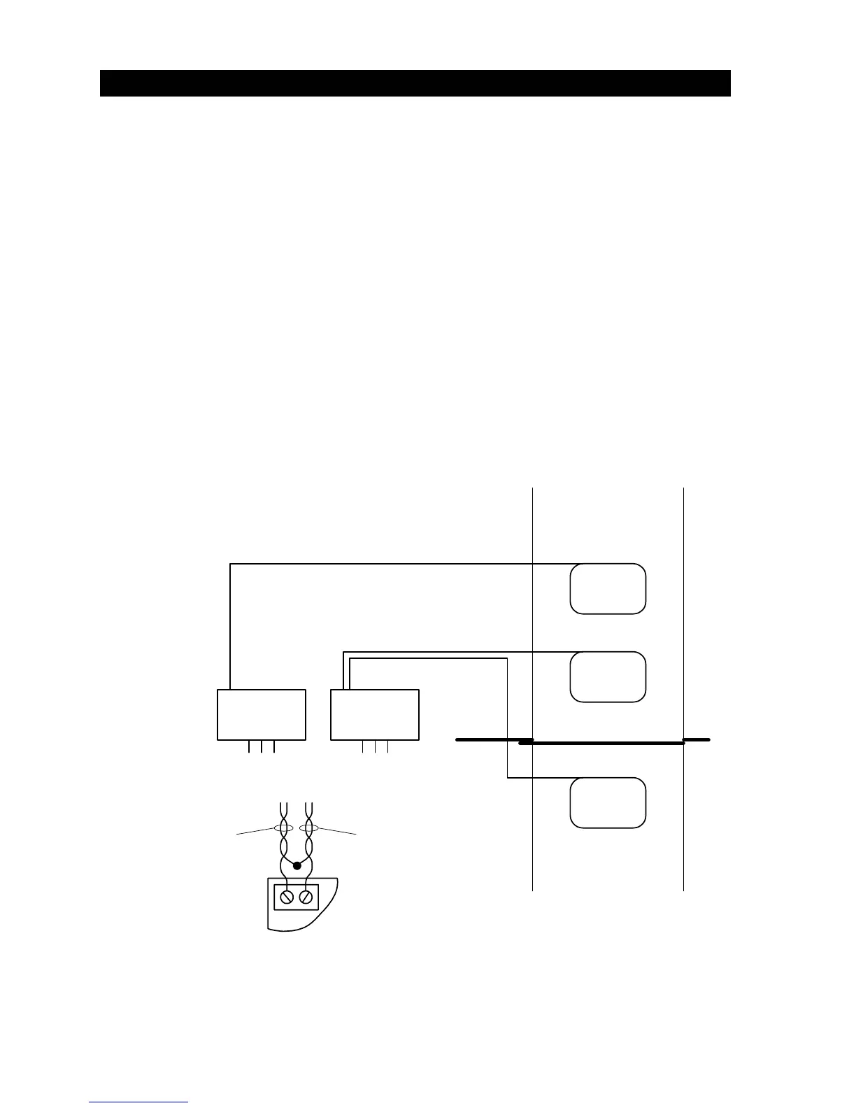
2.4 LOOP DETECTOR WIRING
Loops and loop detectors must be installed with this gate operator to prevent the gate from
accidentally closing on vehicles that may be in the path of the gate.
• Loop detector wiring is shown for DoorKing model 9406 Plug-In loop detector only. If other
loop detectors are used, refer to the installation instructions supplied with those detectors for
wiring requirements.
• If other loop detectors are used, all inputs to the terminal strip are NORMALLY OPEN. Use a
separate power supply to power external detectors. Be sure that power is turned off prior to
making any connections to the terminal strip.
• Loop layout shown is for a typical slide gate application with two-way traffic or one-way exit
only traffic. For one-way entry only traffic, the open loop and loop detector are not needed.
• Refer to the separate Loop Information Manual (available from DoorKing) for instructions on
installing loops or preformed loops.
• Reverse loops are wired in series (detail A)!
Reverse
Reverse
Open
Loop Detector
P/N 9406-010
Loop Detector
P/N 9406-010
TB 1
TB 1
Detail A
Plug into
OPEN Port
Plug into
REVERSE Port
Detail A
TB 1
From inside
Reverse loop
From outside
Reverse loop
Figure 28
18