CellCom‑LTE
Programming and Installation Guide Digital Monitoring Products
11
PROG
B
R
RESETLOAD
+DC- Z1
Z2 Z3
G
T
R
+Z4-
O1 O2
+DC- Z1
Z2 Z3
G
T
R
+Z4-
O1 O2
CellCom
ETHERNET
DSC PC1864
AC AC +AUX- +BELL- RED BLK YELGRN 1 PGM 2 3 PGM 4 Z1 COM Z2 Z3 Z4 Z5 Z6 Z7 Z8
EGND RING TIP
R-1 T-1COM COM COM
AC +AUX-
+BELL- RED BLK YEL GRN 1 PGM 2 3 PGM 4 Z1 COM Z2 Z3 Z4 Z5 Z6 Z7 Z8
EGND
A
RING
B
TIP
C
R-1
D
T-1
COM COM COM
1k Ω
EOL
5.6k Ω EOL
To AC
Power
From DC +
From DC -
From Z4 +
From Z4 -
From T
To RED
To BLK
To YEL
To TIP
To RING
To GRN
From R
RED
BLACK
BLACK
BLACK
YELLOW
GREEN
GREEN
RED
Remote
Programming
Connection
(Model 330-DSC)
PC LINK
1
CON 4
YELLOW
GREEN
YELLOW
GREEN
TAB
UP
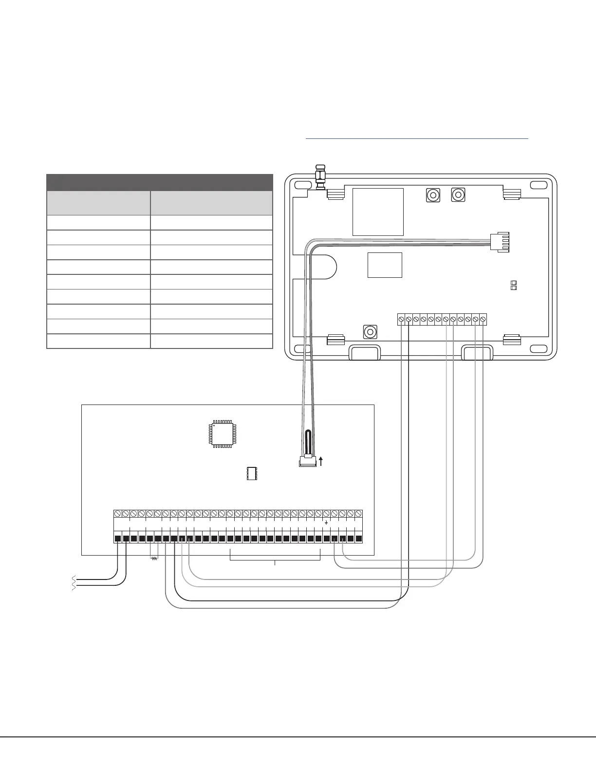
Figure 9: DSC Passthru Wiring
COMMUNICATOR TO DSC WIRING
Communicator
Terminal
DSC Terminal
DC+ RED
DC‑ BLK
Z4+ YEL
Z4‑ GRN
T or T1 TIP
R or R1 RING
N/A Bell+ to Bell‑ (1k Ω EOL)
N/A Zones 1 ‑ 8 (5.6k Ω EOL)
PROG PC Link (COM) Tab Up
Table 4: DSC Terminal Connections
DSC Passthru Connection
The communicator can be connected to the DSC Bus of a DSC PowerSeries Model PC1616, PC1832, or PC1864. Refer
to Table 4 and Figure 9 for wiring details.
Configuration
To configure the communicator for DSC Passthru, set KEYPAD INPUT to DSC and use the DSC SETUP feature in the
Diagnostics (DIAG) menu. For details, refer to “Keypad Input” and “DSC Setup”.
For more about configuring DSC Passthru systems, refer to COM Series How‑To Guide: DSC Passthru (LT‑2208).