CellCom‑LTE
Programming and Installation Guide Digital Monitoring Products
9
ECP Passthru Connection
The communicator can be connected to the ECP Bus of a compatible VISTA panel. Refer to “VISTA Panel
Compatibility” for VISTA compatibility details. See Table 3 and Figure 8 for wiring details.
Configuration
To configure the communicator for ECP Passthru, set KEYPAD INPUT to ECP, program VISTA keypad device
address20, then use the ECP SETUP feature in the Diagnostics (DIAG) menu. For details, refer to “Keypad Input” and
“ECP Setup”.
For more information about configuring ECP Passthru, refer to COM Series How‑To Guide: ECP Passthru (LT‑2209).
PROG
B
R
RESETLOAD
+DC- Z1 Z2 Z3
G
T
R
+Z4-
O1 O2
DualCom
1 2 3 4 5 6 7 8 9 10 11 12 13 14 15 16 17 18 19
20
21 22 23 24
25
+ +–
HI
HI
HI
LO
LO
LO
LO
HI
HI
LO
LO
HI
HI
LO
LO
HI
TIP
(BROWN)
RING
(GRAY)
TIP
(GREEN)
RING
(RED)
+
-
BLACK
RED
SYNC
COM
DATA
(USE SA4120XM-1
CABLE)
1 2 3 4 5 6 7 8
OUT 17
+12 AUX
GND
OUT 18
VISTA 20P ONLY
VISTA-20P
From DC+
From DC–
From Z4+
From Z4-
To Data In (6)
To Data Out (7)
To Negative (4)
To Positive (5)
RED
BLACK
GREEN
YELLOW
RED
BLACK
GREEN
YELLOW
RED
BLACK
GREEN
YELLOW
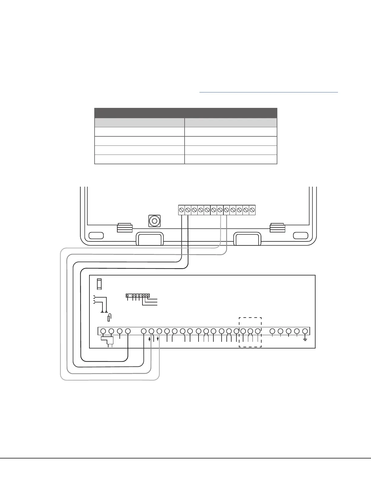
Figure 8: ECP Passthru Wiring
COMMUNICATOR TO ECP WIRING
Communicator Terminal VISTA Terminal
+DC Keypad Power
‑DC Keypad GND
Z4+ Data Out
Z4‑ Data In
Table 3: ECP Terminal Connections