Digital Monitoring Products
CellCom‑LTE
Programming and Installation Guide
4
INSTALLATION
Select a Location
Install the communicator away from metal objects. Do not mount the communicator inside or on a control panel metal
enclosure. Mounting the communicator on or near metal surfaces impairs cellular performance.
Mount the Communicator
The communicator should be mounted to a wall using the included #6 screws in the mounting holes. See Figure 1.
Mount the communicator in a secure, dry place to protect the communicator from damage due to tampering or the
elements. It is not necessary to remove the PCB when installing the communicator.
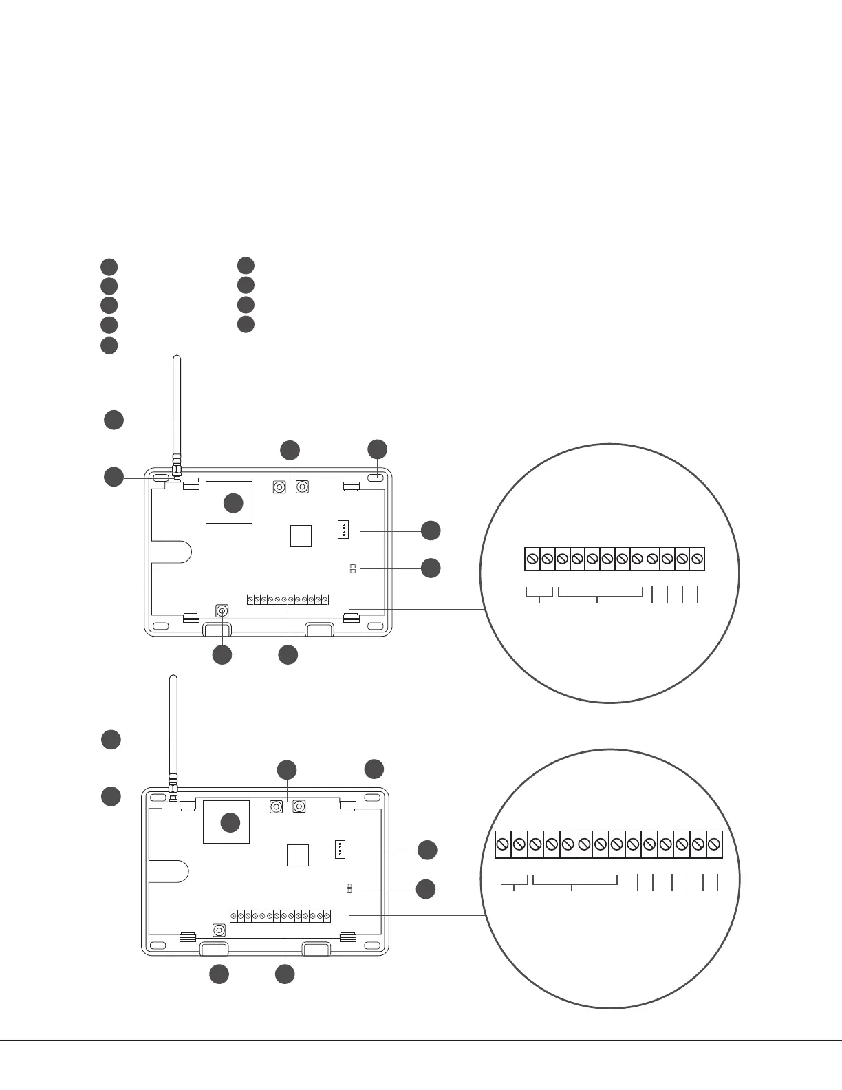
Figure 1: System Components
+DC- Z1 Z2 Z3
G
T R
+Z4-
O1 O2
+DC- Z1 Z2 Z3 G T1 R1 T2+Z4- R2O1 O2
B
C
PROG
B
R
RESETLOAD
D
H
A
GE
+DC- Z1 Z2 Z3
G
T
R
+Z4-
O1 O2
F
I
CellCom-LTE-V
PROG
B
R
RESETLOAD
D
F
H
B
C
A
GE
+DC- Z1 Z2 Z3 G T1 R1 T2+Z4- R2O1 O2
CellComF-LTE-V
A
B
C
D
E
F
G
H
Mounting Holes
Cellular Antenna
SMA Connector
Cell Modem
Tamper
Programming Connection
Terminal Block
Load and Reset Buttons
I
Power and Armed LEDs
I
DC Power
Zones 1 - 4
Tip 1
Output 1
Output 2
Ring 1
DC Power
Zones 1 - 4
Tip 1
Output 1
Output 2
Ring 1
Tip 2
Ring 2