XR150/XR550 Series Installation Guide Digital Monitoring Products
9
INSTALLATION
4.3 Connecting LX-Bus™, AX-Bus™ and Keypad Bus Devices
Connections for LX-Bus/AX-Bus and Keypads are provided through the PROG, LX500, LX600, LX700, LX800, and LX900
4-pin headers and the keypad bus. Several factors determine the DMP LX-Bus/AX-Bus and keypad bus performance
characteristics: the wire length and gauge used, the number of devices connected, and the voltage at each device.
When planning an LX-Bus/AX-Bus and keypad bus installation, keep in mind the following information:
1. DMP recommends using 18 or 22-gauge unshielded wire for all LX-Bus/AX-Bus and keypad circuits. Do not use
twisted pair or shielded wire for LX-Bus/AX-Bus and keypad bus data circuits.
2. On keypad bus circuits, to maintain auxiliary power integrity when using 22-gauge wire do not exceed 500
feet. When using 18-gauge wire do not exceed 1,000 feet. To increase the wire length or to add devices, install
an additional power supply that is listed for Fire Protective Signaling, power limited, and regulated (12 Vdc
nominal) with battery backup.
Note: Each panel allows a specic number of supervised keypads. Add additional keypads in the unsupervised
mode. Refer to the Keypad Bus section for the specic number of supervised keypads allowed.
3. Maximum distance for any one bus circuit (length of wire) is 2,500 feet regardless of the wire gauge. This
distance can be in the form of one long wire run or multiple branches with all wiring totaling no more than
2,500 feet. As wire distance from the panel increases, DC voltage on the wire decreases. Maximum number of
LX-Bus/AX-Bus devices on the rst 2,500 foot circuit is 40 devices.
4. Maximum voltage drop between the panel (or auxiliary power supply) and any device is 2.0 Vdc. If the voltage
at any device is less than the required level, add an auxiliary power supply at the end of the circuit. When
voltage is too low, the devices cannot operate properly.
For additional information refer to the LX-Bus/AX-Bus/Keypad Bus Wiring Application Note (LT-2031).
4.4 Wireless Keypad Association
Enable Wireless Keypad Association operation on the keypad and panel.
To enable wireless keypad association operation on a LCD Wireless keypad (Models 9060 and 9063), press and hold
the Back Arrow key and CMD until SET BRIGHTNESS displays. Enter the code 3577 (INST) and press CMD. Press KPD RF to
start the RF survey communication. The keypad displays its wireless serial number and RF SURVEY.
To enable association operation on a Wireless Graphics Touchscreen keypad (Model 9862), access the Options menu
through the carousel menu. While in the Options display, press the Installer Options icon. Enter the code 3577 (INST)
and press CMD. Press KPD RF to start the RF survey communication. The keypad displays its wireless serial number and RF
SURVEY.
The keypad Power/Armed LED turns Red, indicating communication has not yet been established with the panel
receiver. When successful communication has been established, the Power/Armed LED turns Blue on Graphics
keypads or Green on LCD keypads.
To enable wireless keypad association operation on the XR150/XR550 panel reset the panel three times allowing the
keypad bus transmit light to begin ashing between each reset.
For 60 seconds the panel listens for wireless keypads that are in RF Survey mode and have not been programmed or
associated into another panel. When the keypad associates with the panel the keypad logo LED turns from Red to
Green.
Wireless keypads are assigned to the rst open device position in Device Setup automatically based upon the order in
which they are detected.
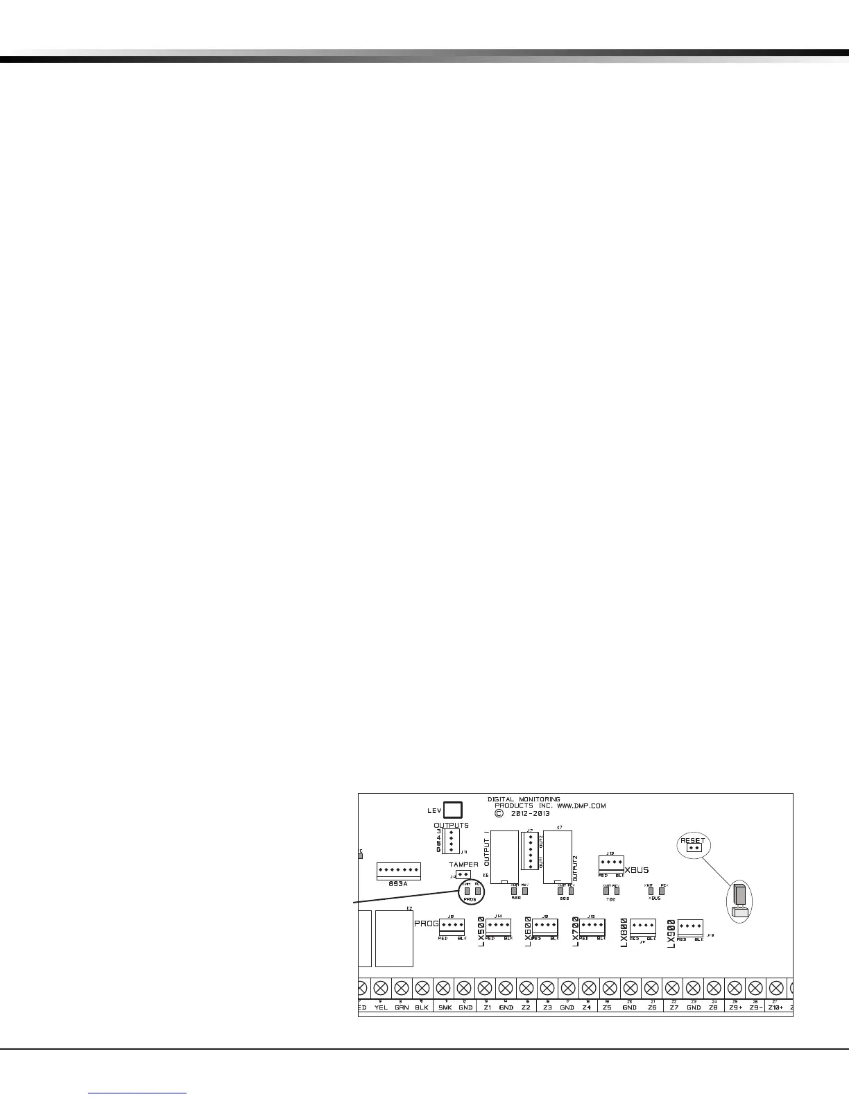
Transmit/Receive LEDs
Figure 5: XR550 Series Panel Showing Reset and Transmit/Receive LEDs