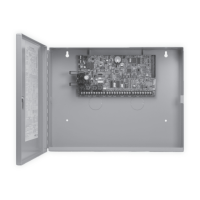
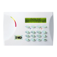
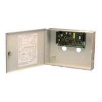
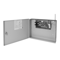
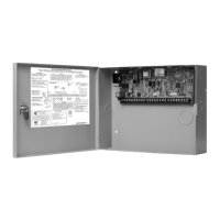
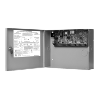
Digital Monitoring Products XR150/XR550 Series Installation Guide
ii
TABLE OF CONTENTS
Protection Zones
10.1 Terminals 13–24 .......................................................................16
10.2 Operational Parameters .............................................................16
10.3 Zone Response Time .................................................................16
10.4 Keyswitch Arming Zone .............................................................16
Powered Zones for 2-Wire Smoke Detectors
11.1 Terminals 25–26 and 27–28 ......................................................17
Dry Contact Relay Outputs
12.1 Description ...............................................................................17
12.2 Contact Rating .........................................................................17
12.3 Model 431 Output Harness Wiring ..............................................17
Annunciator Outputs
13.1 Description ...............................................................................18
13.2 Model 300 Harness Wiring ......................................................... 18
13.3 Model 860 Relay Module ...........................................................18
Wireless Bus Expansion
14.1 Description ...............................................................................18
14.2 Wireless Bus LEDs ....................................................................18
LX-Bus
TM
/AX-Bus
TM
Expansion
15.1 LX-Bus/AX-Bus Headers ............................................................19
LX-Bus (XR150/XR550) .............................................................19
AX-Bus (XR550 V111 or higher): ................................................19
15.2 Device Addressing ....................................................................19
15.3 LX-Bus/AX-Bus LEDs .................................................................20
15.4 OVC LEDs ................................................................................20
ETHERNET Connector (Panels with Network/Encryption only)
16.1 Description ...............................................................................20
16.2 Ethernet LEDs ..........................................................................20
16.3 Network Transient Suppression .................................................. 20
PHONE LINE RJ Connector
17.1 Description ...............................................................................21
17.2 893A or 277 Connector .............................................................21
17.3 Notication ..............................................................................21
17.4 Phone Line Monitor ................................................................... 21
17.5 FCC Registration .......................................................................22
RESET and TAMPER Headers
18.1 RESET Header ..........................................................................22
18.2 TAMPER Header .......................................................................22
Cellular Modules
19.1 CELL MODULE Header ..............................................................23
19.2 Module Installation ...................................................................23
19.3 Connecting the Antenna ............................................................ 23
Wi-Fi Connection
20.1 763 Module to EXP Header ........................................................23
20.2 Connecting the 763 ..................................................................24
20.3 Status LED ...............................................................................24
20.4 Mounting the 763 .....................................................................24
Certications
Export Control
 Loading...


