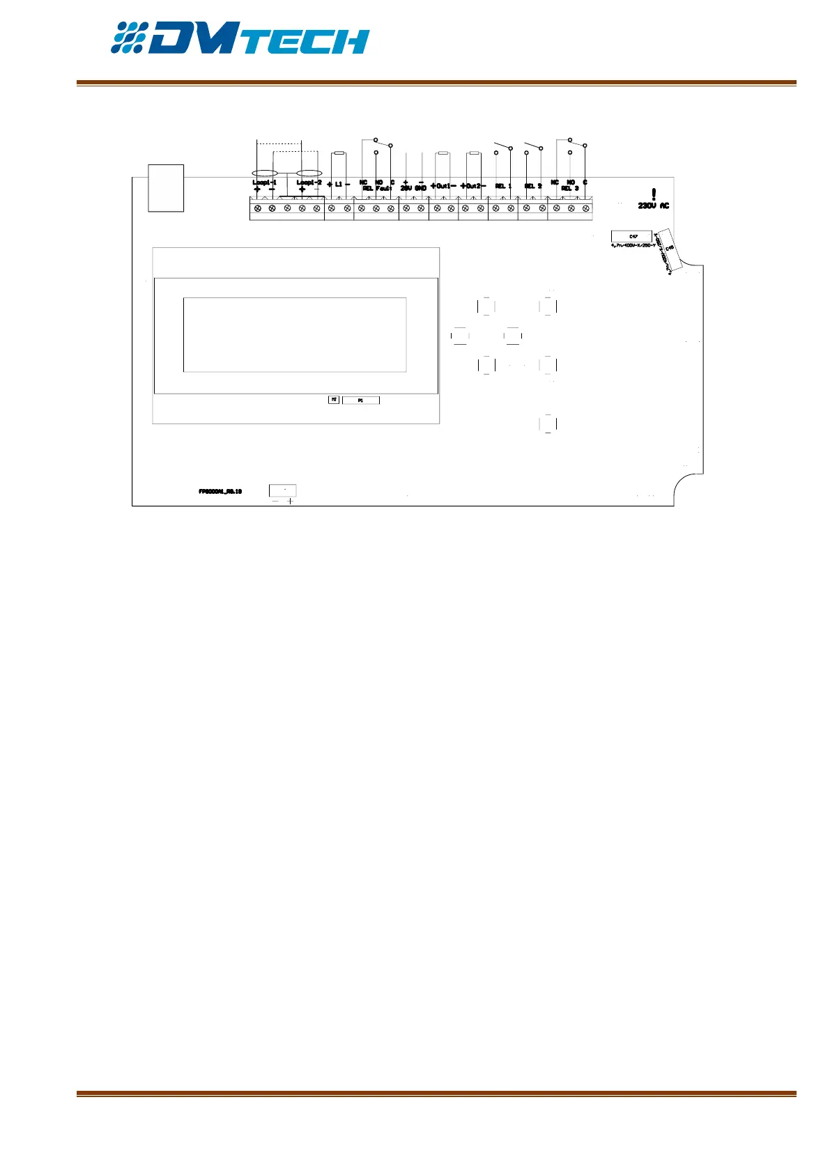
Fig. 6 – Main PCB of the fire alarm panel
Terminal strip description (from left to right):
• LOOP 1 (-LOOP+ / +ERT / -LOOP+) – Terminal strip for connecting Loop 1 to the fire alarm panel.
• LINE – Conventional line
• FAULT – Potential output connecting external devices, 24 VDC/ 0.3А. It is deactivated in fault condition
of in the system.
• 28V – User power supply
• RELAY FAULT - the fault relay is activated when the panel is in fault mode – 3 positions provided for Nc
(default) condition and No condition
• OUT1 – Monitored output OUT1 – a 4.7 кОhm terminating resistor shall be connected in parallel to the
device far off from the panel
• OUT2 - Monitored output OUT2 - a 4.7 кОhm terminating resistor shall be connected in parallel to the
device far off from the panel
• RELAY 1 – Programmable relay 1 – the relay function shall be assigned in settings menu
• RELAY 2 – Programmable relay 2 – the relay function shall be assigned in settings menu
• RELAY 3 – The relay is activated in fire mode. 3 No terminals are provided, Normally open contact, Nc
normally closed contact and center.
• USB –USB B/ micro connector; communication with the fire alarm panel from a computer via specialized
software
• BATT – Pin connector (red and black pins) for connection to the storage battery. An additional Ø5mm
cable ear connector is installed to each cable terminal (M5)