Instruction manual
Fire Alarm Panel FP9000A
DMTech LTD, 16 N.Haytov Street, Pleven Tel.: 0889992660 e-mail:office@dmtech-ltd.com page - 13 - of 20
ISO 9001:2015 Certified Company
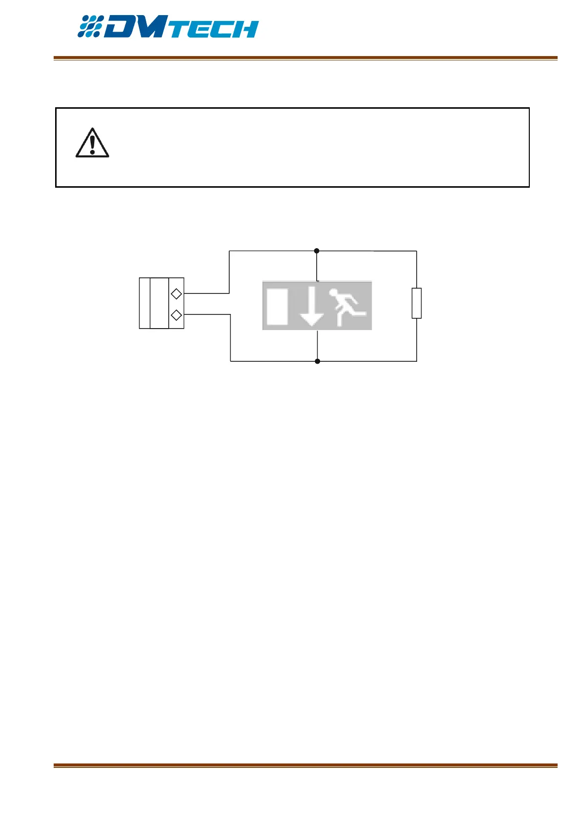
2.3.3. Connecting signaling devices
Signaling or other devices can be connected to each monitored output OUT 1, OUT2 - Fig. 10. Device’s
maximum consumption shall not exceed 0.5A. A 4.7 кОhm terminating resistor must be connected in
parallel to the loop.
Fig. 10 – Example of an exit sign device connected to an output
Monitored outputs OUT1 and OUT2 provide 24VDC 0.5A to load, connected between
them and a mass*.
A 4.7 кОhm terminating resistor shall be connected in parallel to the device far off
from the panel in the loop, so the panel is able to check the loop integrity – see Fig.10.