Instruction manual
Fire Alarm Panel FP9000A
DMTech LTD, 16 N.Haytov Street, Pleven Tel.: 0889992660 e-mail:office@dmtech-ltd.com page - 5 - of 20
ISO 9001:2015 Certified Company
2. INSTALLATION
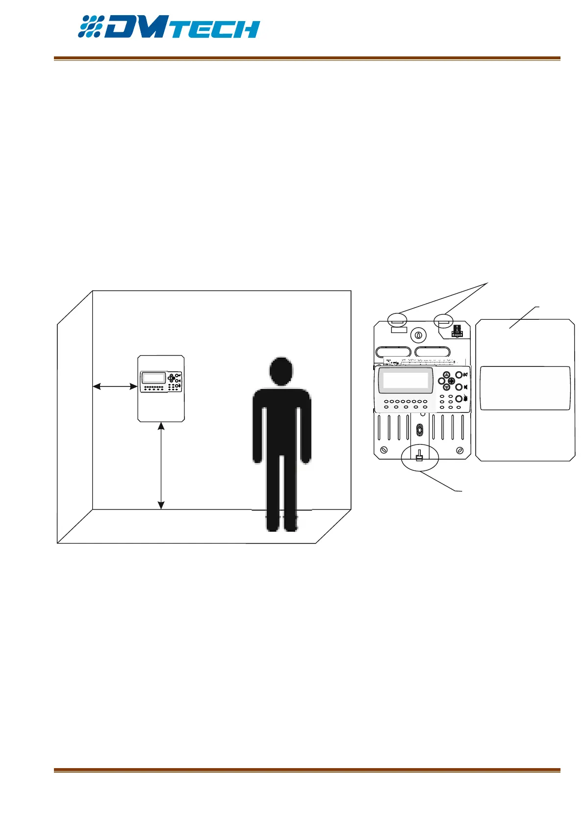
2.1. Mounting
• Choose the most suitable location for the fire alarm panel in the premise (Fig. 1), away from heating appliances,
points of dust accumulation or access to water; ambient temperature between -5°C and +40°C. Warning: the
fire alarm panel is not waterproof!
• Unpack the panel and inspect the unit for any visible damages caused during transportation or due to long-term
shelf storage.
• Open the front lid (Fig. 2).
• Remove the front lid by unscrewing the screw under the front panel (Fig. 2, position 3).
ESC
FIRE
1
DIST FIREFAULT TEST DISABLE
2 3 4 5 6 7 8 POWERSYS ERR
TRANSMCOMMUN
OUTSDELAY OUTON
1500mm
300mm
ESC
FIRE
1
DIST FI RE FAULT TEST DISABLE
2 3 4 5 6 7 8 POWER SYS ERR
TRANSMCOMMUN
OUTS DELAY OUT ON
N
L
Fuse 4A
FP9000A
1
3
2
Fig. 1 Fig. 2
• In compliance with the dimensions provided in Fig.3 drill holes in the mounting surface.
• Drill holes in the wall and fasten the box.
• All external cables must be pulled through in the box, to make the connection, BUT DO NOT CONNECT THEM
TO POWER YET. THE POWER CABLE MUST BE PULLED THROUGH THE DESIGNATED HOLE AND MUST
BE KEPT AWAY FROM LOW VOLTAGE CONNECTIONS.
• Connect the power supply and the ground to power supply terminal (see Fig.3), but do not supply power yet.
• Put the backup batteries in place.
• Replace the front lid by mounting the lid to the circuit board box and fasten with the screw following the
description on Fig.2 in reverse order.
• Proceed to initiation and testing of the system.