Instruction manual
Fire Alarm Panel FP9000A
DMTech LTD, 16 N.Haytov Street, Pleven Tel.: 0889992660 e-mail:office@dmtech-ltd.com page - 7 - of 20
ISO 9001:2015 Certified Company
2.2. System elements
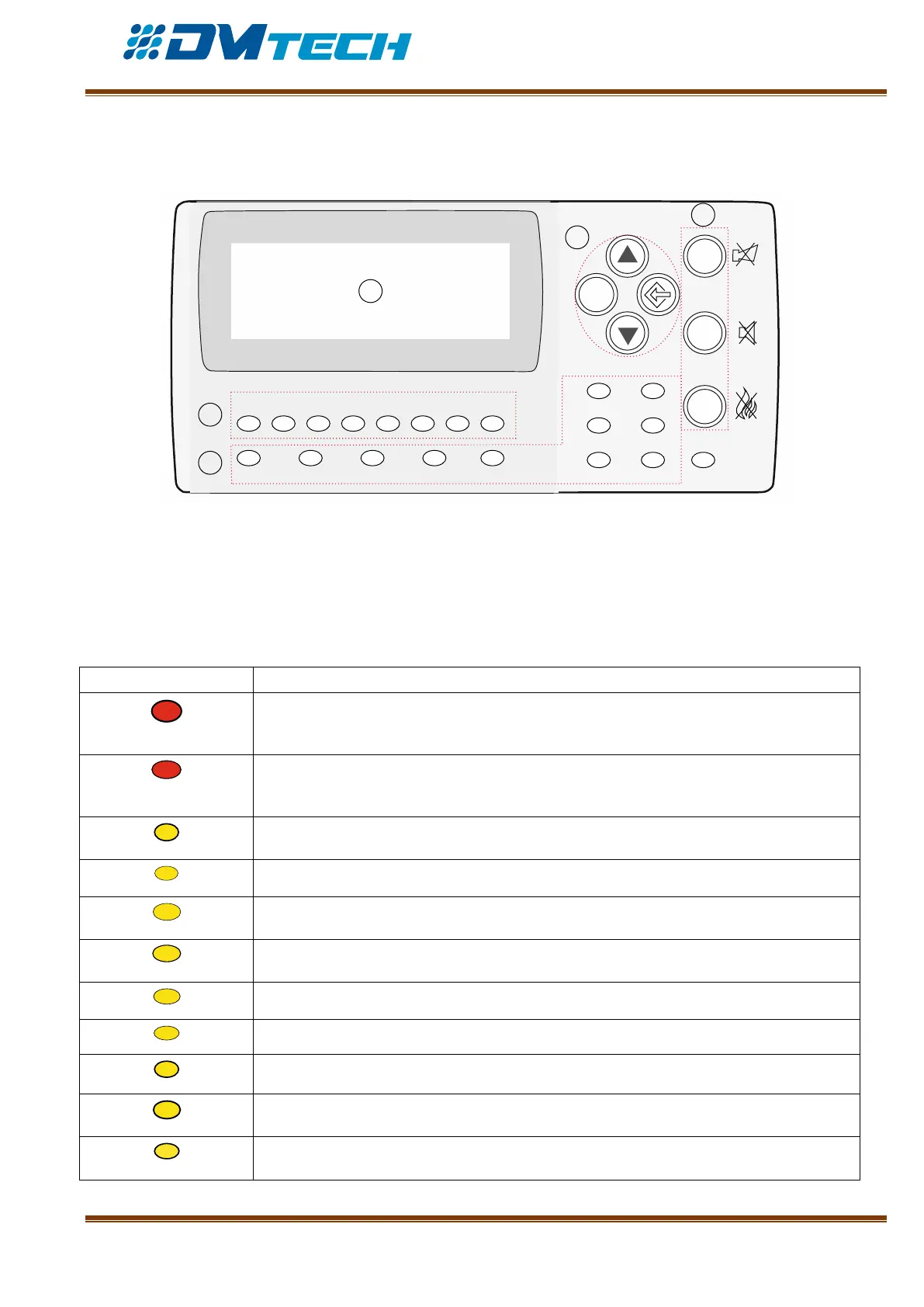
2.2.1. Front panel – front panel is shown on Fig. 4. Puncture line separates logically buttons and
indicators according to their purpose.
ESC
FIRE
1
DIST FIRE FAULT TEST DISABLE
2 3 4 5 6 7 8
POWER SYS ERR
TRANSM COMMUN
OUTS DELAY OUT ON
1
2
3
5
4
Description of elements:
1 – LED indicators with events description
2 – LED indicators for zones
3 – Alphanumeric LCD display (4х20)
4 – Functional buttons
5 – Navigation and control buttons
Fig. 4
1 – Description of LED indication of events:
FIRE INDICATOR. Illuminates continuously in case of alarm for fire event, after
received signal from automated fire detector, manual call point or from another
external device connected to panel’s output
DISTANT FIRE INDICATOR. Illuminates continuously in red, in case of alarm for fire
event in a distant fire alarm panel, after received signal from automated fire detector,
manual call point or from another external device connected to distant panel’s outputs
FAULT. Illuminates continuously in yellow, in case of fault event in the system
TEST. Illuminates continuously in yellow upon system testing
Disabled component – Disabled Component indicator illuminates in continuous yellow
light
FAULT IN POWER SUPPLY. Illuminates in continuous yellow light in case of fault
condition in 220V main supply or battery
CPU FAILURE. Illuminates continuously in case of CPU failure (System Error)
Signal for fire event is being transmitted to a remote center
Data communication via LAN – continuous yellow light
Fault condition in controllable outputs – the indicator for fault in controllable outputs
illuminates in continuous yellow light
The indicator for output delay illuminates in continuous yellow light