Instruction manual
Fire Alarm Panel FP9000A
DMTech LTD, 16 N.Haytov Street, Pleven Tel.: 0889992660 e-mail:office@dmtech-ltd.com page - 8 - of 20
ISO 9001:2015 Certified Company
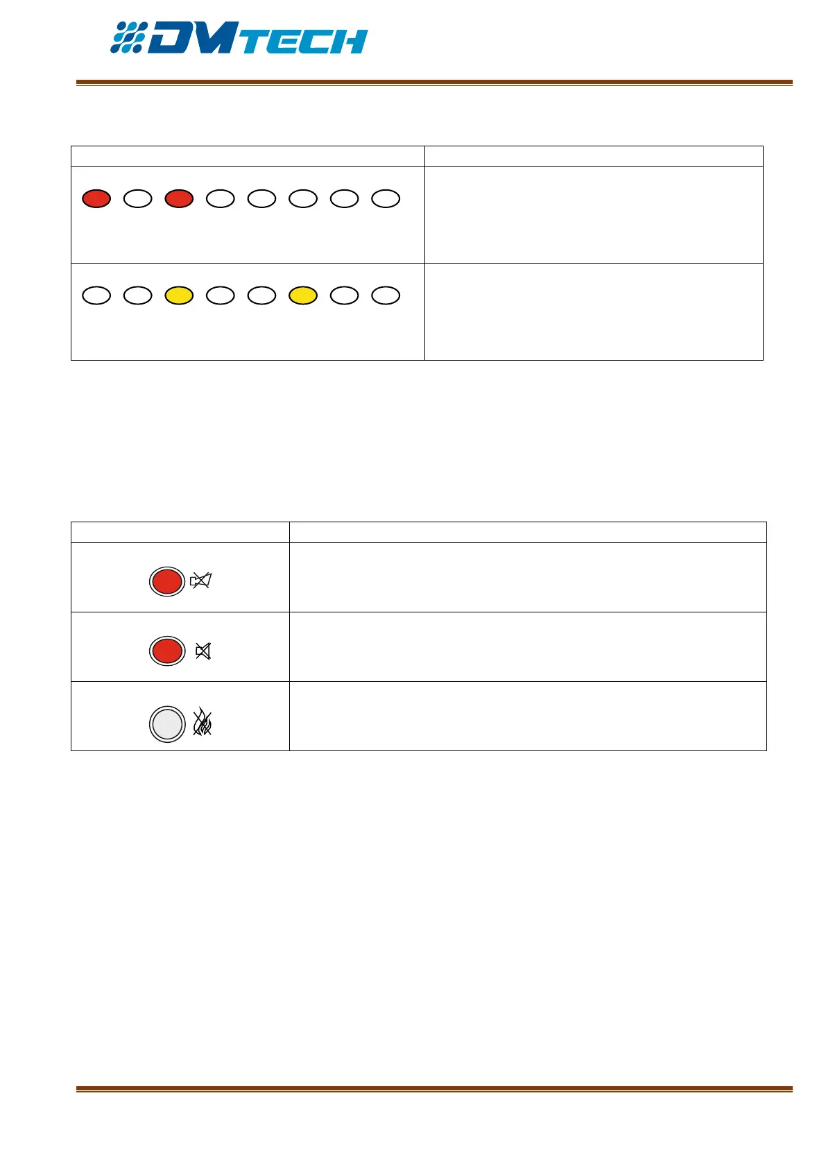
2 – Description of LED indication for zones in use:
ZONE IN FIRE CONDITION. Separate indicators
for fire condition in zones 1-8 – in case of fire they
illuminate in red light and the sounder releases a
continuous signal.
ZONE IN FAULT CONDITION. In case of fault
condition the indicator for the relevant zone 1-8
illuminates in yellow and the sounder releases an
interrupted signal.
3 – Description of LCD display
The fire alarm panel has an alphanumeric LCD display (4 lines x 20 symbols). It displays information on
registered events. The display visualizes menus for panel settings (menus are tree-structured, see Fig.11) that
can be accessed consecutively using the navigation buttons. The user can assign freely names to zones and
devices, using the buttons for navigation and control.
4 – Description of functional buttons:
Functional button for sounder silencing – illuminates in red when silenced
Fire condition and Fault condition - Functional button for suppressing the
local sounder – illuminates in red
Functional button for Fire Alarm Mode resetting. Requires access level 2
password.