Instruction manual
Fire Alarm Panel FP9000A
DMTech LTD, 16 N.Haytov Street, Pleven Tel.: 0889992660 e-mail:office@dmtech-ltd.com page - 9 - of 20
ISO 9001:2015 Certified Company
5 – Description of navigation and control buttons:
The button is for entering the MENU option. It also acts as an
OK/confirmation button.
The button increases a highlighted value with one step, or enables access
to an ascending menu.
The button decreases a highlighted value with one step, or enables access
to a descending menu.
The button is for exiting the menu. It is active at access level 1,2 and 3.
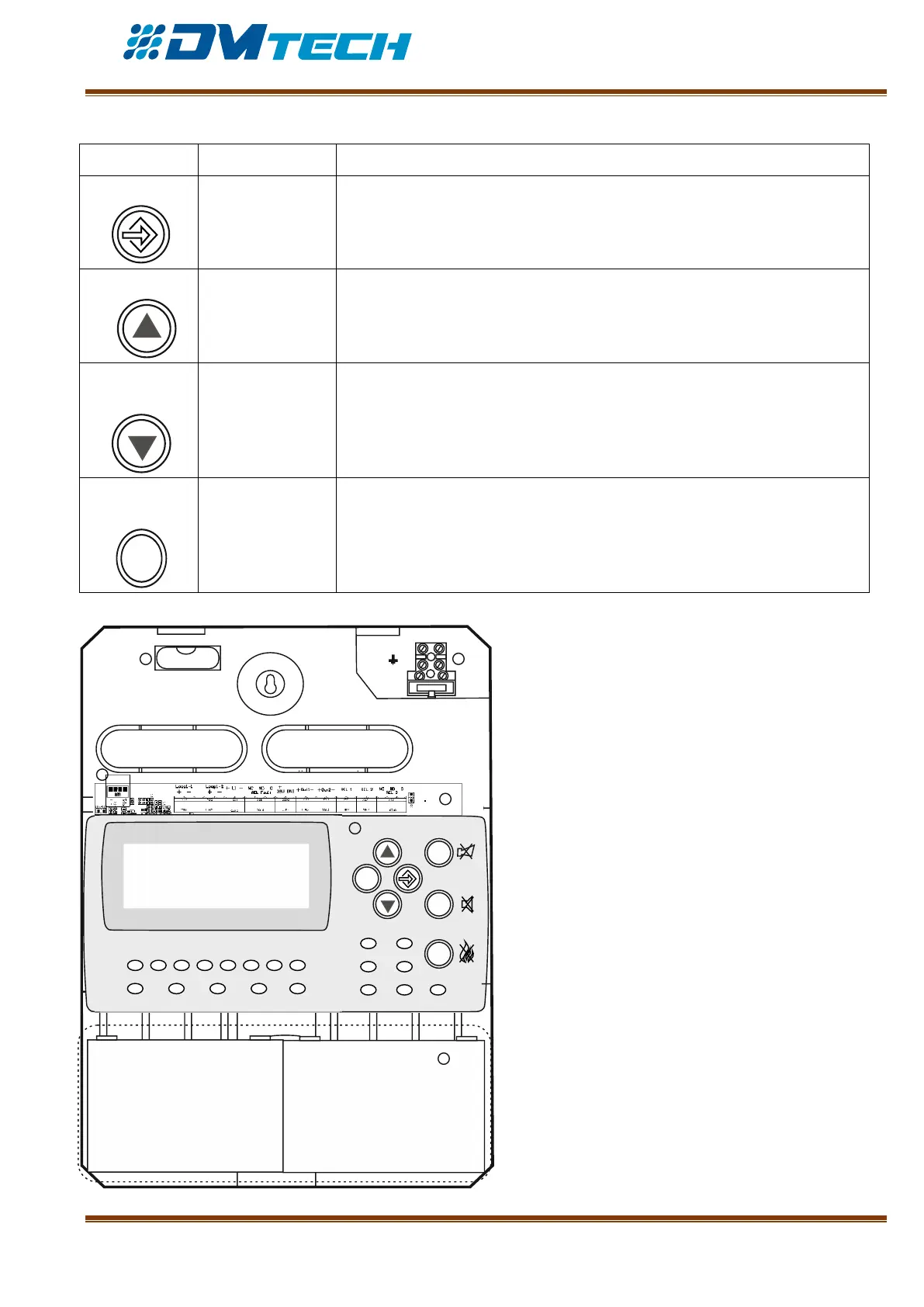
2.2.2. Position of modules in the box
Fig. 5 – Position of modules in the box:
1 – Box leveling ampule;
2 - 220V terminal for main power supply cable
3 – Main PCB with built-in power supply
4 – Chassis with ready-to-use alphanumeric
display window, waveguides for light indication,
buttons
5 – Space for storage batteries, 2 х 12V/ 4.5–5Ah
6 – Coupling for USB connection to a computer
ESC
FIRE
1
DIST FIRE FAULT TEST DISABLE
2
3
4
5 6
7
8
POWER SYS ERR
TRANSM COMMUN
OUTS DELAY OUT ON
12V 4.5-5 Ah
12V 4.5-5 Ah
+
+
--
N
L
Fuse 4A
1 2
3
4
5
6