Operation Manual
VacuDAP 2002
2002BA01e.DOC / 22.07.2004 6 of 22
2 Preparation of operation
2.1 Preparation
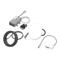
The VacuDAP 2002 measuring system comprises the following components:
• Ionization chamber
• Detector electronics
• Display unit
• Cable (signal line) for connecting the detector electronics to the display unit
• Plug-in power pack
• Optional accessories (see 6, Accessories and options)
Remove the packing material carefully. Should any components found to be damaged, contact the
supplier or manufacturer. Damaged components may not be used.
2.2 Supply voltage
For powering the measuring system VacuDAP 2002, a plug-in power pack is offered which meets the
IEC 60601-1-1 standard. The length of the power pack's connecting cable is approx. 1.8 m.
Alternatively, an extra-low voltage ranging between +15 V ... +24 V can be tapped from the X-ray unit
provided this power supply complies with the European standard for medical electrical devices
IEC 60601-1, is short-circuit-proof, and has a current-carrying capacity of ≥ 300 mA (in case of a 2-
channel measuring system 956 00 01: ≥ 500 mA). Further requirements can be found in Chapter 1.4,
Protection against electric shock.
The supply voltage is applied by means of a power pack connector (outer diameter: 5.5 mm; pin
diameter: 2.5 mm) the centre contact (pin) of which carries the positive potential (+15 V ... +24 V). The
reference potential (ground, GND) is that of the metallic housing parts of the display unit and the
housing of the electronics.
The measuring system is provided with an internal polarity reversal protection.
2.3 Installation
The measuring system shall be installed by a duly qualified person.
The dimensions of the ionization chamber are dependent on the specifications of the X-ray unit and
the used absorber. The following sizes for different absorbers are available:
Order-No. Active area Absorber Notes
159 00 11 Ø 68 mm 2-4 mm plastic transparent
159 00 13 Ø 106 mm 2-4 mm plastic transparent
159 00 05 Ø 44 mm 3 mm aluminium non-transparent
159 00 08 Ø 44 mm 2-4 mm plastic non-transparent
159 00 09 Ø 72 mm 2.8 mm aluminium non-transparent
159 00 12 Ø 72 mm 2-4 mm plastic non-transparent
Table 1: Circular ionization chambers