Operation Manual
VacuDAP 2002
2002BA01e.DOC / 22.07.2004 7 of 22
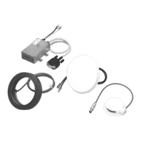
The ionization chamber is intended for the installation within the collimator (behind the beam limiting
device). If the reference direction of incident radiation is specified in the annexed data sheet of
ionization chamber it is crucial that the ionization chamber is installed accordingly.
The display unit should be put up or installed in a suitable place.
The ionization chamber is connected to the detector electronics. The female connector of the signal
line (cable 953 00 40) is connected to the male connector of the detector electronics and screw-
locked, whereas the male connector of the signal line is plugged into the 4-pole socket of the display
unit.
Make sure the cable is laid such that it is stress-relieved. The cable must
not restrict the movement of the arm supporting the X-ray source.
2.4 Function test
All components of the measuring system should have reached room
temperature before the function test is started.
If the VacuDAP 2002 measuring system was correctly installed the supply voltage can be applied.
After an initialisation phase, the measuring system starts the POWER-ON TEST (see 3.3.3, TEST
function) during which the correct connection and function of all system components are automatically
tested.
When the function test is correctly performed, the following messages - among others - will be
displayed:
VACUDAP
:
TEST OK
RESET
0
and the VacuDAP 2002 measuring system switches to the MEASURE mode.
In case of a trouble, an error message with an up to four digit number (shown as
xxxx), which
characterizes the trouble, will be displayed:
ERR:xxxx
One cause of this message may be an incorrect installation of the system. Troubleshooting should be
performed as described in Chapter 5.1, Error codes and troubleshooting.
2.5 Installation and testing of accessories
Any accessories supplied with the system (e.g. a printer) are connected to the serial interface of the
display unit with the associated cable (see 6, Accessories and options) which is plugged into the 5-
pole socket of the unit. For any other installation work see the descriptions supplied with the
respective equipment.