'3
DoALL INSTRUCTION MANUAL
ROLLER SAW GUIDES:
1. Select correct rollers for the width of blade
to
be used.
2. Place
one
back-up and
one
side roller in
each block.
3
.
After the guides
are
placed
on
the machine,
place the
saw
band
over
the wheels and
adjust the tension.
4. Turn the roller
cams
to
bring the rollers
up
to
the blade. The rollers should be just
free enough
to
turn
without moving the
blade.
5. Tighten the roller lock
screws
and adjust
the upper wheel tilt until the
saw
tracks
just touching the flange
on
the back-up
roller.
SPIRAL SAW GUIDES:
The rubber tired rollers
are
mounted
on
‘ball bearing shafts. The rubber tires
are
grooved
to
properly guide the blade.
1. When the
saw
guides
are
installed, place
the band in position, apply
a
light tension,
same
as
for 3/16" blade, and track the
band until
it
rides freely in the grooves of
the rollers. One roller
on
each guide has
an
eccentric shaft. Loosen
set
screw
on
guide block and
turn
eccentric with
a
screw
driver until the band rides the bottom of
the groove on_ both rollers. Be
sure
the
cutting edges of the band
are
facing clown
to
the table when the band revolves.
TRACKING
AND
TENSIONING
THE
BLADE
To facilitate tracking the blade
onto
the
wheels, the upper
saw
wheel is tiltable in and
out
as
well
as
adjustable up and down.
A
handwheel
at
the
center
of the upper wheel
(and
rear
on
3 wheel models) adjusts the
wheel tilt and
a
handwheel below the frame
head adjusts the band tension. To properly
“track” the blade
on
either 2
or
3 wheel
models proceed
as
follows:
1. Release clamp bar
at
front edge of table,
shift machine
to
neutral and place
a
120"
band
over
the drive and upper wheels. Take
up slack in the band with the tension hand-
wheel.
2. Turn wheels by hand.
If
the blade
starts
turning the
saw
guide thrust bearings
or
if
there is
a
noticeable gap between the blade
and the thrust bearings, adjust with the tilt
handwheel. Turning this handwheel clock-
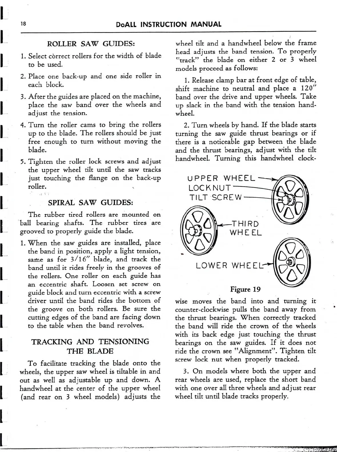
U PPER WHEEL
LOCKNUT
TILT ‘SCREW
Figure 19
wise
moves
the band into and turning
it
counter-clockwise pulls the band away from
the thrust bearings. When correctly tracked
the band will ride the
crown
of the wheels
with its back edge just touching the thrust
bearings
on
the
saw
guides.
If
it
does
not
ride the
crown
see
“Alignment”. Tighten
tilt
screw
lock
nut
when properly traclced.
3. On models where both the upper and
rear
wheels
are
used, replace the short band
with
one
over
all three wheels and ad
ust
rear
wheel tilt until blade tracks properly.