DoALl INSTRUCTION MANUAL 23
wheels. One of these sections
can
be removed
to
convert
the file band for two-wheel
use
when
a
wide throat clearance is
not
needed.
On the 36-3 model the auxiliary guard
shown in Fig. 2 is used for
two
wheel opera-
tion.
The Job Selector Dial will indicate the
correct
file bands
to
be used for the proper
filing of
common
materials. For special work,
the Band Tool Manual should be consulted.
The available sizes and types
are
as
follows:
Half
Flat Round Oval
3/8II_]/2” 3/SI! 3/3N_]/2"
Short Angle 10 teeth
Bastard
I
2 teeth 3/3"
Bastard 14 teeth %
”
373
"-
1/;
’’
Bastard 1 6 teeth 3/3
"
%”
'
Bastard 20 teeth %
"-
%'i
Bastard 24 teeth 1A”
SETTING UP THE'MACI-IINE
FOR FILING
s
The following steps should be followed for
both internal and external filing:
I.
If
the machine is already
set
up for
sawing,
remove
the
saw
blade, then
remove
the top and bottom
saw
guides from the
upper and lower posts.
2. With the transmission shifted
to
neutral,
‘
mount
the file guide support,
as
shown in Fig.
25,
on
the lower post block making
sure
the
proper width of slot for the file band is being
used.
3. Lower the upper post of the machine
to
the proper work thickness. This thickness
should
not
exceed
two
inches when
a
1/4" file
band is being used. Longer guides
are
avail-
_...
.-
.
r
I
--
;‘7’v‘>-¥a‘:.-'-"I.:-:1
.
-'
-
able that will permit 1'':
ling of 7" thicknesses
with the 1/4" band
and 8" thicknesses
“W70”
\
with the 3/8" and
,_
—:_-;»._
'”"
°”'°‘
l/2”
bands.
,
_7;f;':5’/ rgbggéggt
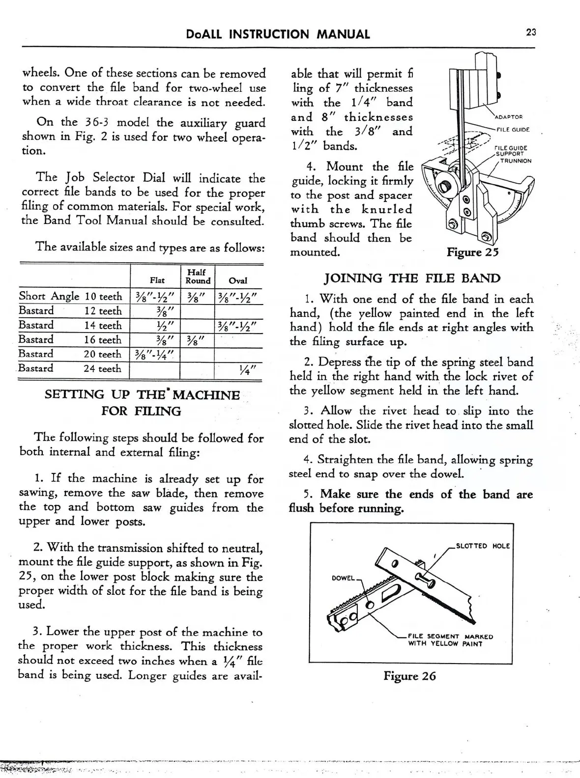
4. Mount the file
TRUWON
guide, locking
it
firmly
to
the post and spacer
,
Q
with
the
knurled
Q
thumb
screws.
The file
band should then be 53
mounted. Figure 25
JOINING
THE
FILE BAND
1.
With
one
end of the file band i.n each
hand, (the yellow painted end in the left
hand) hold the file ends
at
right angles with
the filing surface up.
'
2. Depress the tip of the spring steel band
held in the right hand with the lock rivet of
the yellow segment held in the left hand.
3. Allow the rivet head
to
slip into the
slotted hole. Slide the rivet head into the small
end of the slot.
4. Straighten the file band, allowing spring
Stefil. Cnd
to
Snap
Over
the d0WeL
.
5. Make
sure
the ends of ‘the band
are
flush before running.
FILE SEGMENT MARKED
WITH YELLOW PAINT
Figure 26