30 DoALL INSTRUCTION MANUAL
This attachment is bolted
to
the post with the
cap screws and washers furnished. Place the
Hat washers against the post
to
prevent
damage. Lower the post until the
saw
guides
are
approximately 3/8" above the table.
Loosen the
two
bolts and
move
the
center
pin
to
approximately the distance of radius
to
be
cut.
Clamp the adjustment housing
tight.
The
center
of the centering pin
must
be
directly in line with the cutting edge of the
saw
blade. To accomplish this,
remove
one
filler plate from the table and place
a
square
against the side of the filler plate slot with the
blade of the square against the tip of the
saw
tooth. Line up the centering pin with the edge
of the square’s blade and clamp tight. Make
final radius adjustments with the fine adjust-
ment
wheel. Tighten the bolt
on
the radius
arm
clamp making
sure
the
center
pin is
square
to
the table. Adjust the
unit
for work
thickness by raising
or
lowering the post.
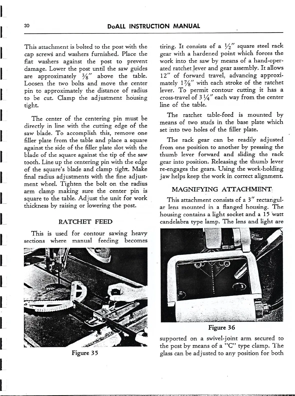
RATCHET
FEED
This is used for
contour
sawing heavy
sections where manual feeding becomes
tiring.
It
consists of
a
1/2" square steel rack
gear with
a
hardened point which forces the
work into the
saw
by
means
of
a
hand-open
ated ratchet lever and gear assembly.
It
allows
12" of forward travel, advancing approxi-
mately 17/3" with each stroke of the ratchet
lever. To permit
contour
cutting
it
has
a
cross-travel of 3 1/1" each way from the
center
line of the table.
The ratchet table-feed is mounted by
means
of
two
studs
in
the base plate which
set
into
two
holes of the filler plate.
The rack gear
can
be readily adusted
from
one
position
to
another by pressing the
thumb lever forward and sliding the rack
gear into position. Releasing the thumb lever
re-engages the gears. Using the work-holding
jaw helps keep the work
in
correct
alignment.
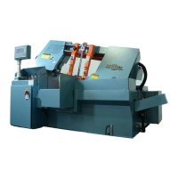
MAGNIFYING ATTACHMENT:
This attachment consists of
a
3" rectangul-
ar
lens mounted in
a
flanged housing. The
housing contains
a
light socket and
a
15 "watt
candelabra type lamp. The lens and light
are
in
Figure 36
supported
on
a
swivel-joint
arm
secured
to
the post by
means
of
a
“C”
type clamp. The
glass
can
be adjusted
to
any position for both
-
'-"-"=""""""='-“'-’-'1""‘>"'.‘.'-
:-
.-.-1--u.v-g....—,