54 999817902 - 10/2022
Scaffold User Information Ringlock
Ringlock Shoring
Shoring Component Overview
The below diagram is a generic example of a Ringlock
Shoring tower. The Ringlock system components and
Shoring accessories are designed to be interchangea-
ble to meet the demands of construction projects
around the world and may require the use of Heavy
Duty Base Jacks and U-Heads. Lift heights can be
adjusted to minimize the number of components
required to suit load resistance requirements.
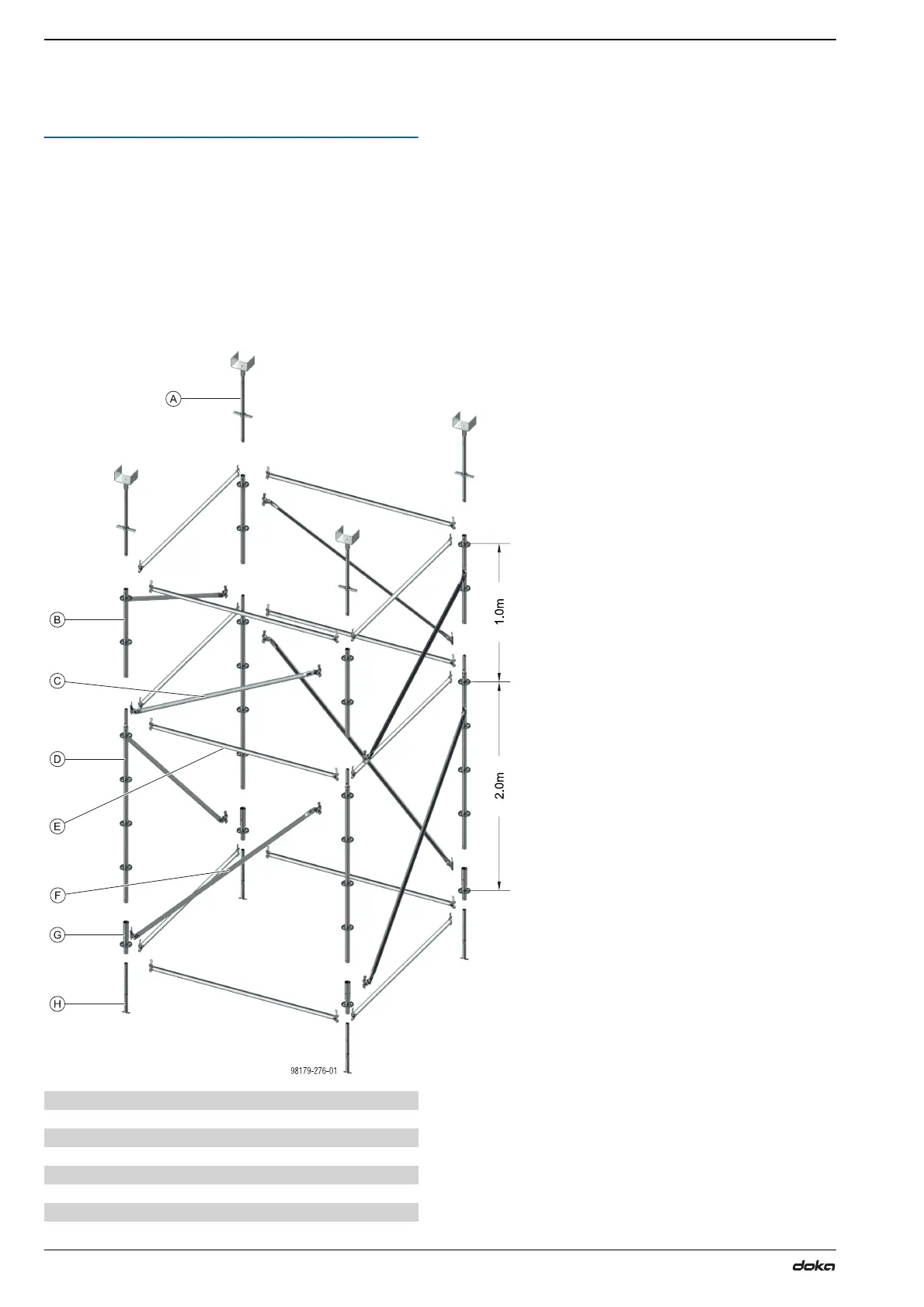
Shoring Tower Assembly Exploded View
A *U-Head Assembly (Dependent on Load Requirements)
B Standard open ended
C Bay Brace 1.0m
D Standard with Spigot
E Ledger
F Bay Brace 2.0m
G Base Collar
H *Base Assembly (Dependent on Load Requirements)