User Manual of DOLCWIUHFP
5
Red LED lighting means the is power on, while Blue LED lighting means the
captures the data of the tag,
1.2.5 Buzzer
When captures the data of the tag, the buzzer will beep.
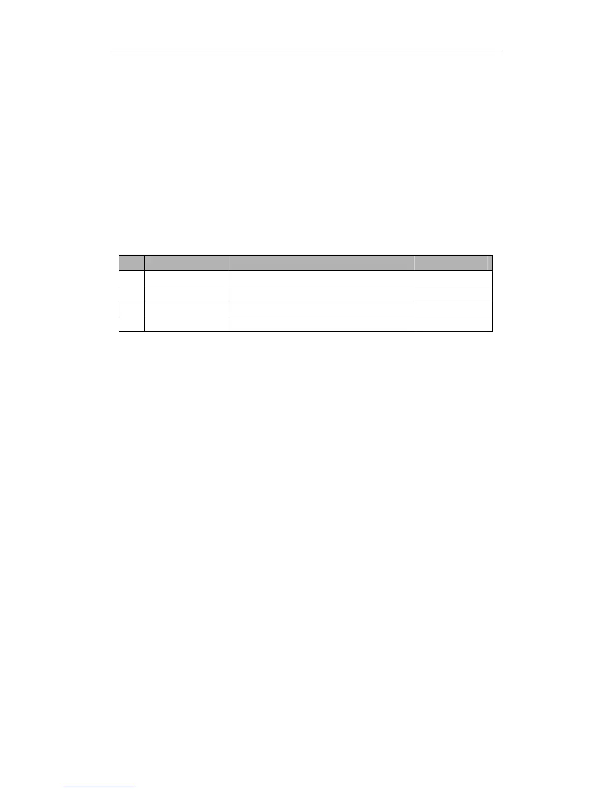
1.2.6 Label
No
Label Type Definition Position
1
SN Label The serial number of the host Back Board
2
Interface Label The specified communication interface of the host Back Board
3
Capital Letter Label A or B or C or D or E Back Board
4
Mode Interval Scan or Trigger Mode Back Board
Remark:
1. The SN label is the identification of each reader, don t tear off during using.
2. Please check the interface configuration with the Interface Label, if not correct, please contact with
Transmitter Solutions.
3. Don t install two hosts with the same Capital Letter Label within 20 meters scope.
4. Trigger Pins reserved for Trigger Mode only.
1.3 Cautions before Using
1. Please use the 12V 4A DC Power for connecting the host with the power.
2. If the DC Power is not waterproof, it is suggested to insert into the Ticket Box or be
covered.
3. The power cord wh
ic
h connected DC Power and the 120V AC Power needs to be
connected the ground wire to prevent lightning strikes.
4. When extending power:
• Up to 100 feet, use 18 AWG, 600 volt insulated wire
• Up to 200 feet, use 16 AWG, 600 volt insulated wire
THE PROPER WIRING IS CRITICAL!
5. Wiegand wire runs are 500 feet maxium. Use 6-conductor stranded wire with overall shield.
18, 20, 22 or 24 gauge is preferred.
DOLCWIUHFP
DOLCWIUHFP
DOLCWIUHFP