ENiQ® Wall Readers & Terminals
_____________________________________________________________________________________
33
Installation
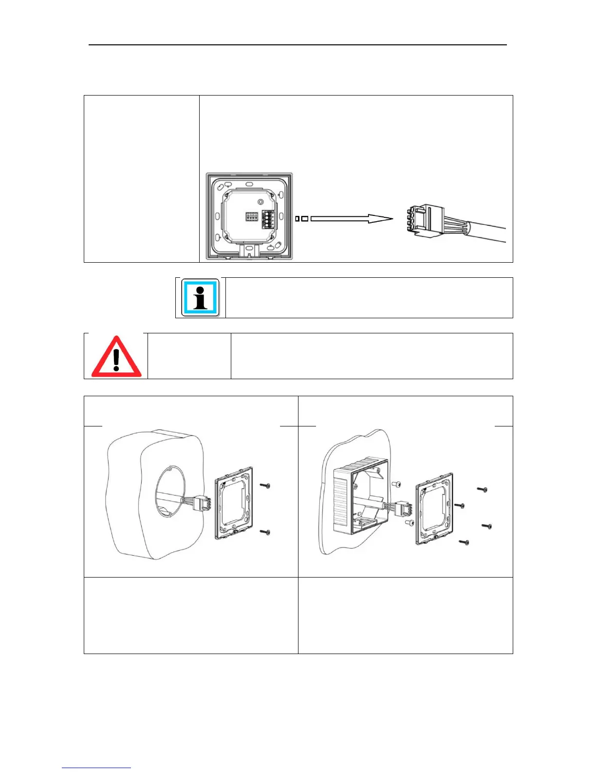
Preparation for
installation
Route the connection cable for voltage supply and RS485
interface accordingly and prepare for connection.
Remove the 4-pole multipole connector from the reading
module and wire it according to the respective wiring diagram
A corresponding connection diagram is included
with every reader
The reader must be wired up in a de-energised state
i.e. the operating voltage may only be switched on after
the reader has been completely installed.
Flush mounted variant
Use the screws provided to screw the
back plate to a DIN device box with a
device screw spacing of 60mm.
Surface mounted variant
Mount the surface mounted casing on the
wall. Screw the back plate to the surface
mounted casing using the screws
provided.