ENiQ® Wall Readers & Terminals
_____________________________________________________________________________________
39
Installation procedure
Preparation for installation
Route the connection cable for interface, voltage routing and separate I/O box
accordingly and prepare for connection.
Pull the front module carefully off the back module and set it to one side.
Check the DIP switches on the back module in accordance with the respective
interface and firmware function and set as required (configuration / address etc.)
Wire up the back module according to the respective wiring diagram.
A corresponding connection diagram is included with every reader
Caution!
The reader must be wired up in a de-energised state
i.e. the operating voltage may only be switched on after the reader has been
completely installed.
Following complete electric wiring of the back module, use the
screws provided to screw it to a standard size 55 flush mounted
box and align horizontally.
Heed the TOP marking
(arrow must be pointing upwards)
Rework the standard intermediate frame in the corners if necessary (depending on
the switch manufacturer or switch range) until the front module can be inserted into
the standard intermediate frame without tension.
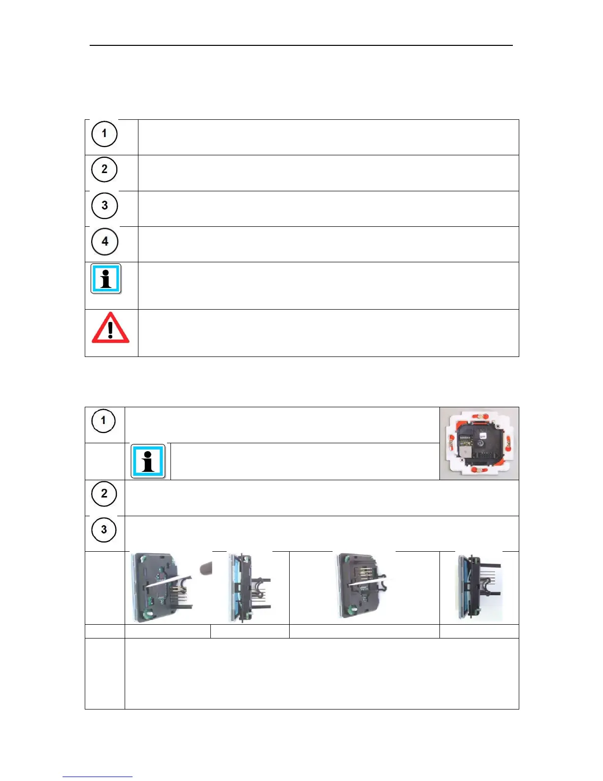
Dismantle the front module, take the transparent cover off the front module (by
releasing the two opposite locking snap-fits)
Step 1: Use the screwdriver to unlock the first locking snap-fit
Step 2: Carefully pull the transparent cover forward by approx. 10mm
Step 3: Turn the front module through 180° and use a screwdriver to release the
second
locking mechanism
Step 4: Carefully pull the transparent cover forward completely