12
RJ-11-6C4P connectors MUST be in-
stalled as shown in (FIG. 7) & (FIG. 8).
e. Plug the 4 conductor communication cable
into one of the RJ-11-6C4P telephone cou-
plers protruding from the return air opening.
If more than one zone is used, the second
coupler is used to join each additional zone.
f. Plug the indoor temperature sensor cable (if
applicable) into the P4 (white) 2 pin match-
ing connector protruding from the return air
opening.
g. Connect the previously run Energy Manage-
ment System wires (if applicable) to the yel-
low wires protruding from the return air open-
ing. The polarity of these connections does
not matter.
h. If an Automatic Generator Start (AGS) kit is
installed, follow installation instructions fur-
nished with AGS kit.
2. 120 Vac Power Supply Connection
a. ELECTRICAL SHOCK HAZ-
ARD. Make sure 120 Vac power is discon-
nected from RV. Failure to obey this warning
could result in death or serious injury.
b. ELECTRICAL SHOCK HAZ-
ARD. Provide grounding in compliance with
all applicable electrical codes. Failure to
obey this warning could result in death or se-
rious injury.
c. Route the previously run 120 Vac power
supply wire through the strain relief and into
the junction box. Tighten strain relief making
sure not to damage wires. Leave enough
wire inside junction box to connect to unit
120 Vac wires.
d. Connect white to white; black to black; and
green to green or bare copper wire using ap-
propriate size connectors.
e. Tape the connectors to the supply wire to en-
sure they don’t vibrate loose.
f. Push wires into the box and install cover.
J. System Conguration
Now that the system is installed, it is necessary to do a
system conguration.
1. Electronic Control Conguration
Depending on the equipment options installed
by the RV manufacturer, the appropriate dip
switches will need to be switched to the “ON”
position. Placing the switch in the “ON” position
selects that option. See (FIG. 21) & (FIG. 22) &
(FIG. 23).
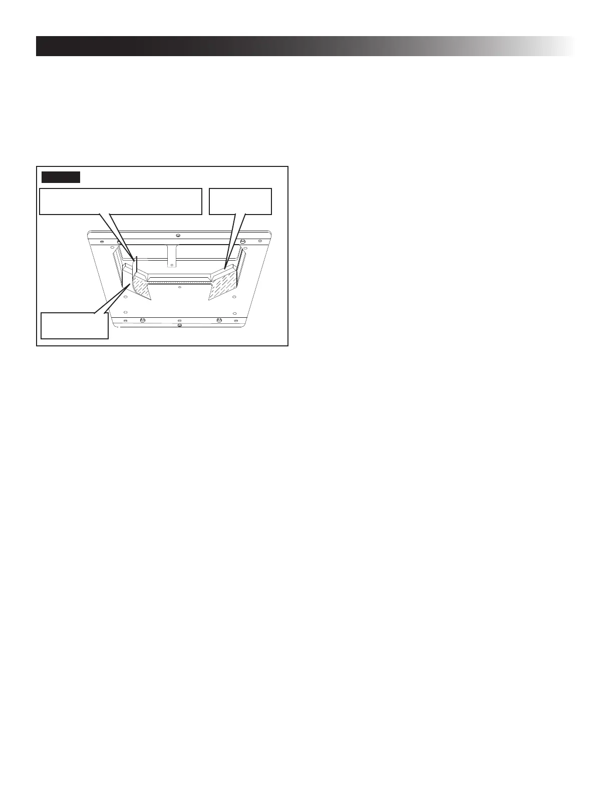
d. With slight pressure push the divider plate
against the double-sided tape on the ceiling
template.
e. Locate the 1/8″ x 7″ x 18″ self-adhesive insu-
lation supplied with the RAG kit. Remove the
backing paper from the insulation and care-
fully stick onto the ceiling template divider
plate. See (FIG. 20).
FIG. 20
Foam Tape
Place Insulation In Position
(Do Not Cover Unit Rating Plate)
Divider Plate
● Excess width is intended to seal the di-
vider plate to the sides of the roof open-
ing. This is to help prevent cold air dis-
charge from circulating into the unit return
air opening.
● If the insulation is too high, stick excess
height of the insulation to the unit base
pan. Do not cover up unit rating plate.
I. Wiring System
Reach up into the return air opening and pull down the
remaining wires. See (FIG. 15).
1. Low Voltage Wire Connections
a. Make sure the positive (+)
12 Vdc terminal is disconnected from sup-
ply battery. Otherwise, damage to unit could
occur.
b. Connect the previously run 12 Vdc wires to
the red and black wires protruding from the
unit return air opening. Connect +12 Vdc to
the red wire; –12 Vdc to the black wire.
c. Connect the previously run furnace wires (if
applicable) to the blue wires protruding from
the return air opening. The polarity of these
connections does not matter.
d. Terminate the 4 conductor communication
cable(s) protruding from the roof opening.
The cable(s) must be terminated with a tele-
phone RJ-11-6C4P connector. Refer to the
crimp tool manufacturer for crimping instruc-
tions.
INSTALLATION INSTRUCTIONS