13
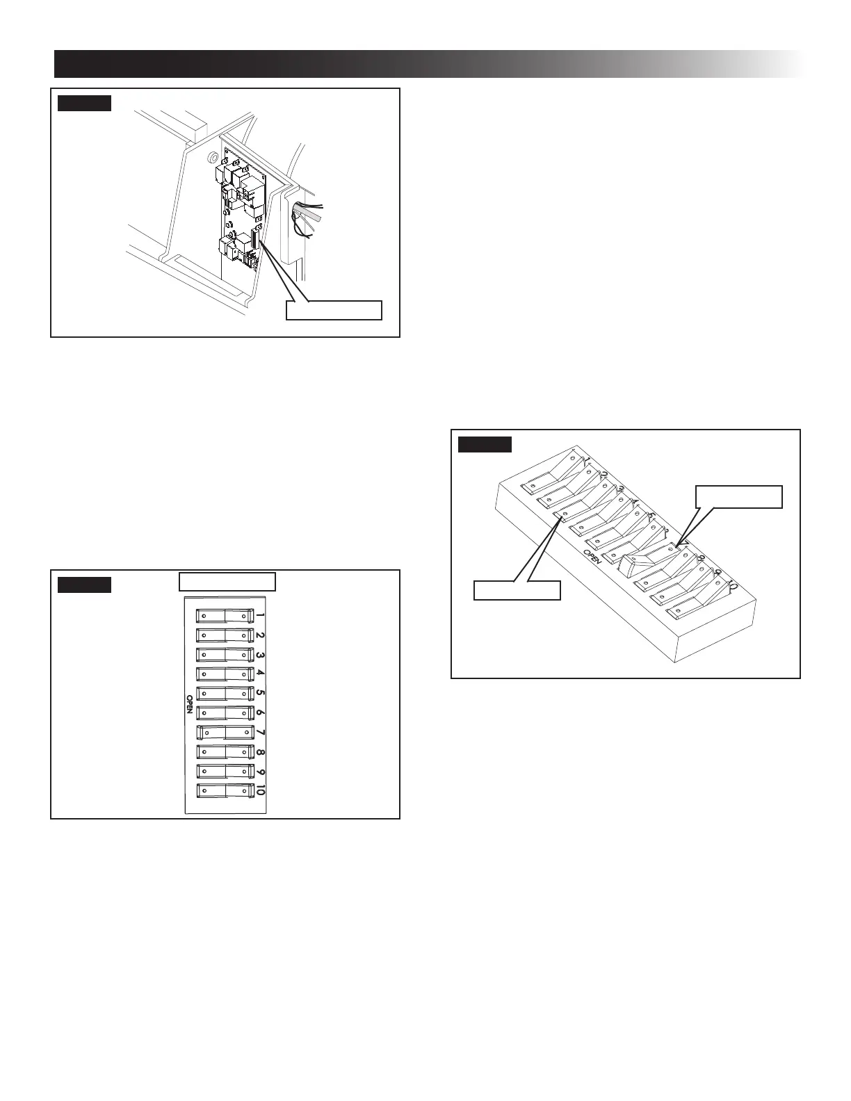
d. Heat Strip - On heat strip models the #6 dip
switch is in the “ON” position from the facto-
ry. Non heat strip models leave in the “OFF”
position.
e. Heat Pump - On heat pump models the #7
dip switch is in the “ON” position from the
factory. Non heat pump models leave in the
“OFF” position.
f. Furnace - If a Furnace/Aqua heat system
has been connected to this unit, the furnace
dip switch must be placed in the “ON” posi-
tion.
g. Dehumidify - Dehumidify is not used on this
unit. Leave in the “OFF” position.
h. Gen Start selection - Leave in the “OFF” po-
sition.
i. Install electronic control box cover.
j. Repeat this procedure for each additional
zone.
FIG. 23
On Position
O Position
K. Installing Return Air Cover
1. Remove the return air grille from the return air
cover.
2. Place the return air cover up to the ceiling tem-
plate.
3. Install cover to template using six (6) supplied
#8 x 3/8″ blunt point Phillips head screws.
4. Re-install lter return air grille into return air cov-
er. Align tabs with mating notches and snap into
place.
5. Install two (2) hole plugs into screw holes in
back of return air cover. See (FIG. 24).
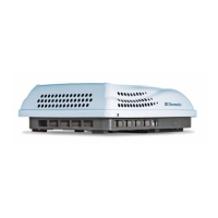
FIG. 21
Dip Switches
Dip switches are in the “OFF position
when shipped from the factory except heat
pump models. On these models the ap-
propriate dip switch is in the “ON” position
from the factory. They are visible through
the opening in the electronic control box.
To gain access to the dip switches on mod-
els with board built in, the out side plastic
shroud MUST be removed from the unit.
Next remove the electrical box cover. The
electrical box will be on the curb side of
the RV after installation. See (FIG. 22).
FIG. 22
Dip Switches
Zone 2
Ext. Stage
Zone 3
Zone 4
Stage
Heat Strip
Heat Pump
Furnace
Dehumidify
Gen Start
a. Ext. Stage - Ext. Stage is not used on this
unit. Leave in the “OFF” position.
b. Zone selection - Each CCC 2 thermostat can
have up to 4 zones. When only one unit is in-
stalled it becomes Zone 1 and no dip switch
setting is required. Each additional unit must
be assigned a zone (2 through 4). Each unit
must have a dierent zone setting.
c. Stage selection - Stage is not used on this
unit. Leave in the “OFF” position.
INSTALLATION INSTRUCTIONS