7
INSTALLATION INSTRUCTIONS
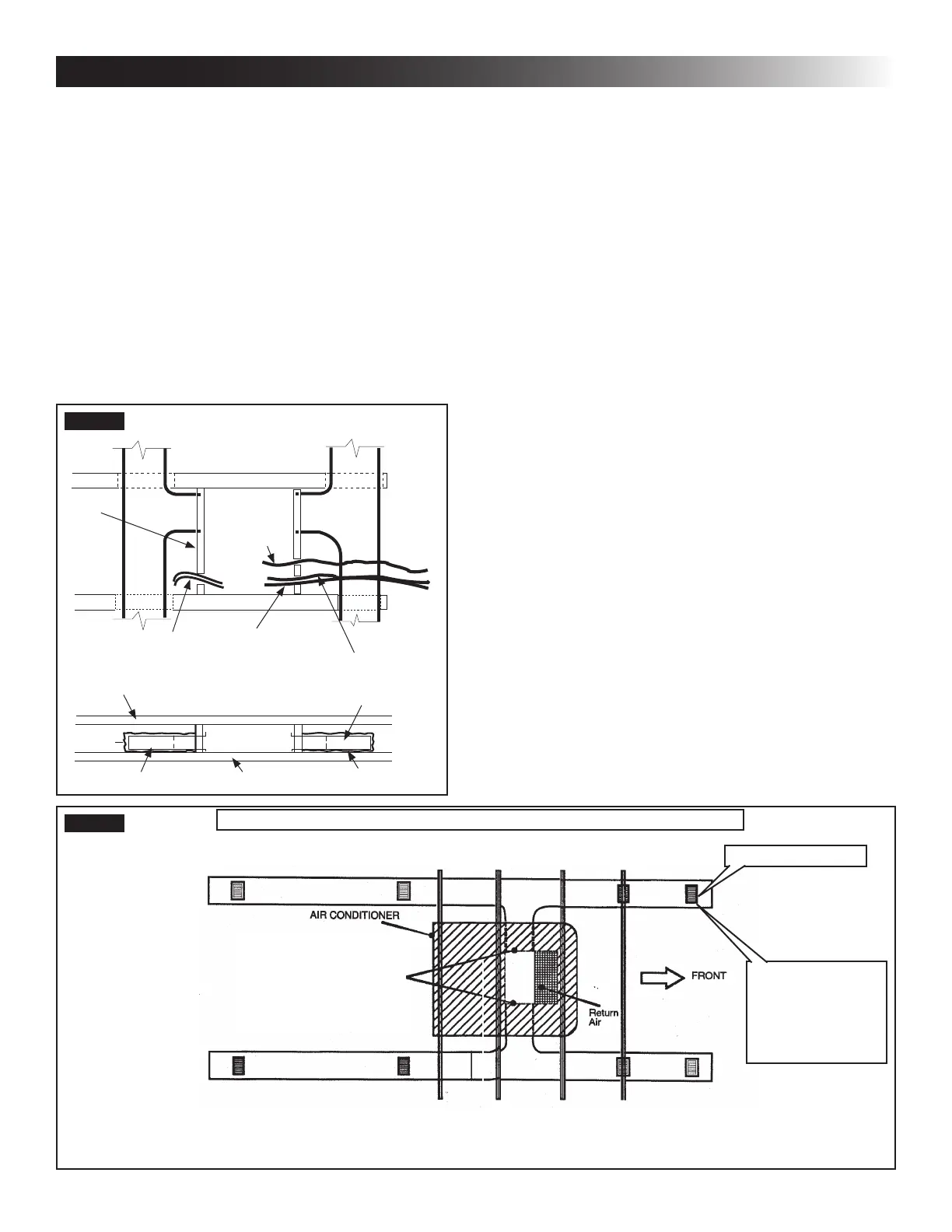
3. Ducts and their joints must be sealed to prevent
condensation from forming on adjacent surfaces
during operation of the unit.
4. Return air openings must have 40 square inches
minimum free area including the lter.
5. Return air to the unit must be ltered to prevent
dirt accumulation on unit cooling surface.
6. Air Distribution System Installation
a. Dometic Corporation recommends the basic
conguration shown in (FIG. 6), for installing
this system. We have found by testing, that
this conguration works best in most applica-
tions. It is the responsibility of the installer to
review each RV oor plan to determine the
following:
● Duct size
● Duct layout
● Register size
● Register location
● Thermostat location
● Indoor Temperature Sensor Location
These items must be determined in conjunc-
tion with the Air Distribution Duct System
Sizing & Design requirements. See “C. Table
- Air Distribution Duct Sizing & Design” on
page (5).
Alternate congurations and methods
may be used which will allow the unit
to operate properly; however, these
alternate congurations and methods
MUST be approved by Dometic Cor-
poration in writing. The following in-
structions are based upon the use of
RAG Kits 3105007.XXX & 3105935.
XXX.
C. Air Distribution Duct Sizing & Design
The installer of this system must design the air distribution
system for their particular application. Several requirements
must be met for the unit to operate properly. These require-
ments are as follows:
1. Make sure ductwork will NOT
bend or collapse during and after installation,
and that it is correctly insulated and sealed.
Otherwise, damage to roof structure and ceiling
could occur.
2. All discharge air ducts must be properly insu-
lated to prevent condensation from forming on
their surfaces or adjacent surfaces during op-
eration of unit. This insulation must be R-7 mini-
mum. See (FIG. 5).
Frame
DuctDuct
Frame
Frame
Roof Opening
Roof Opening
AC Power
Supply Wire
Low Voltage Wires:
12 Vdc
Furnace
Indoor Temperature
Sensor Cable
Communication
Cable
Roof
SIDE VIEW
(TOWARD BACK OF RV
Duct
Ceiling
Duct
Insulation
TOP VIEW
(BACK OF RV)
FIG. 5
FIG. 6
Duct Size And Requirements For 3105007.XXX And 3105935.XXX RAG
Register Required
Registers
4 Min - 8 Max.
(Per Unit)
14 Sq. In. Free
Area Per Register